Insert for a cylinder sleeve or a cylinder of an internal combustion engine

a technology of internal combustion engine and insert, which is applied in the direction of electric ignition installation, mechanical equipment, machines/engines, etc., can solve the problems of difficult production and fitting into the insert, not optimally suited for series production, etc., and achieves simple and cost-effective, reliable

Active Publication Date: 2009-02-03
MAHLE INT GMBH
View PDF14 Cites 8 Cited by
  • Summary
  • Abstract
  • Description
  • Claims
  • Application Information

AI Technical Summary

Benefits of technology

[0011]It is therefore an object of the invention to create an insert for a cylinder sleeve or a cylinder of an internal combustion engine, which can be produced and assembled in a simple and cost-effective manner, achieves a reliable effect, and can be used in many different ways.

Problems solved by technology

Such inserts are difficult to produce and fit into the sleeve, because of the close tolerances in production and assembly, and therefore are not optimally suited for series production.

Method used


Image

  • Insert for a cylinder sleeve or a cylinder of an internal combustion engine
  • Insert for a cylinder sleeve or a cylinder of an internal combustion engine
  • Insert for a cylinder sleeve or a cylinder of an internal combustion engine

Examples


Embodiment Construction

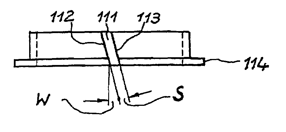
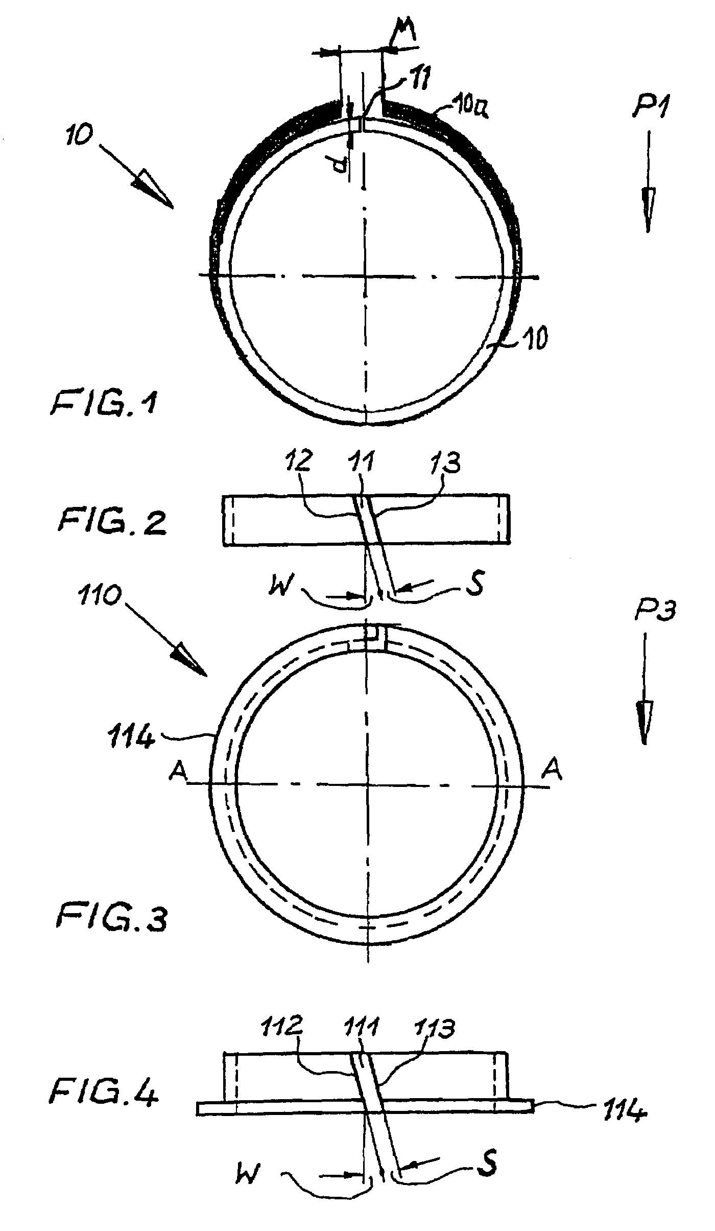
[0036]Referring now in detail to the drawings, FIGS. 1 and 2 show a first embodiment of an insert 10 according to the invention. Reference symbol 10a shows the non-biased ring. Insert 10 is a punched part made from sheet steel having a sheet thickness d of 0.4 to 0.7 mm. In this embodiment, insert 10 is made for a cylinder sleeve 20 having an inside diameter of 130 mm. Insert 10 is punched out as a sheet-metal strip, and formed into an open, biased ring 10 either in the same work step or subsequently. Insert 10 has a ring joint 11 that is determined by its joint ends 12, 13. In the assembled state, ring joint S is dimensioned in such a manner that it is not completely closed, but rather a certain joint play remains, so that joint ends 12, 13 of the insert 10 do not touch even in the case of heat expansion during operation. Joint ends 12, 13 of the ring joint 11 that face one another run at a defined angle (W) parallel to one another (cf. FIG. 2). With this, a closed contour of the i...


PUM


Abstract

An insert for a cylinder sleeve or a cylinder of an internal combustion engine is provided for narrowing the diameter of the cylinder sleeve or cylinder in the region of the upper dead center of a piston guided in the cylinder sleeve or cylinder. The insert is formed as an open, biased ring having a ring joint, which ring is held radially by means of its radial forces, which act outward, and axially by a recess in the cylinder sleeve or cylinder, in such a manner that the radial surface pressure is approximately the same on the circumference, whereby its ratio of ring wall thickness (d) to inside diameter (D) of the cylinder sleeve or the cylinder amounts to between 0.001 and 0.02.

Description

BACKGROUND OF THE INVENTION[0001]1. Field of the Invention[0002]The present invention relates to an insert for a cylinder sleeve or a cylinder of an internal combustion engine, for narrowing the diameter of the cylinder sleeve in the region of the top land at the upper dead center of a piston guided in the cylinder sleeve. Such an insert serves to strip off carbon that accumulates on the top land, and prevents contact of the carbon with the working surfaces of the cylinder sleeve or the cylinder.[0003]2. The Prior Art[0004]An insert of this type is described in U.S. Pat. No. 3,489,130. This reference describes a piston / cylinder arrangement for internal combustion engines, to which a ring-shaped insert is assigned in order to form a narrowed segment of the inside wall of the cylinder.[0005]A combined device consisting of a sealing element towards the cylinder head and carbon stripper is described in U.S. Pat. No. 4,474,147. For this purpose, the closed ring insert is structured angle...

Claims


Application Information

Patent Timeline
Patent Type & Authority Patents(United States)
IPC IPC(8): F02P1/00F02P5/00
CPCF02F1/00F02F1/16F02F1/166F16J10/04F02F2001/006F02B77/04F02F1/18
Inventor BISCHOFBERGER, ULRICHSTAPELBROEK, KAY
Owner MAHLE INT GMBH
Why Eureka
Try Eureka