Micro fluid chip

a micro fluid chip and fluid chip technology, applied in chemical/physical/physical-chemical processes, chemical apparatus and processes, transportation and packaging, etc., can solve the problems of inability to increase throughput, and inability to achieve desired flow rate, etc., to achieve favorable molecular diffusion of liquids and high efficiency

Inactive Publication Date: 2009-02-03
HITACHI LTD
View PDF4 Cites 7 Cited by
  • Summary
  • Abstract
  • Description
  • Claims
  • Application Information

AI Technical Summary

Benefits of technology

[0010]Therefore, it is an object of the invention to provide a micro fluid chip that can process liquids of large flow rates at high speed and eliminates large-sizing of an apparatus.
[0014]When liquids arranged alternately in the liquid supply are decreased in dimension in a direction of arrangement as they go downstream, the respective liquids arranged alternately become small (a diffusion length is shortened) in width in the direction of arrangement. And so it is liable to consider that diffusion is favorable in progress, but a flow passage decreases in cross sectional area in a flow direction when dimensions in a direction intersecting the direction of arrangement and the flow direction are maintained in the flow direction. Then, pressure loss increases to make flow at large flow rate impossible.
[0015]Hereupon, dimensions in the direction intersecting the direction of arrangement and the flow direction are increased in the flow direction so that the flow passage is made the same or slightly large in cross sectional area in the flow direction, whereby an increase in pressure loss is prevented and liquids at large flow rates can be made to flow.
[0017]When a cross sectional area of a connection of a succeeding processing portion and the flow flattening portion in a direction intersecting the flow be maintained up to a liquid discharge port, contact areas, per unit length in the flow direction, of adjacent liquids can be maintained also in the processing portion, so that a stagnation time until termination of mixing or reaction of the respective liquids supplied from the liquid supplies can be shortened and the flow passage in the processing portion is decreased in length, thereby enabling making an apparatus small in size.
[0018]Accordingly, since liquids can be made to flow at high speed and a flow rate, of which a single micro fluid chip can dispose, is increased, it is possible according to the invention to reduce the number of parallel processings to avoid large-sizing of an apparatus.
[0021]Besides, since contact area between the high-viscosity liquid and the low-viscosity liquid are increased, molecular diffusion of the liquids is favorable in progress to be able to cause desired mixing and reaction of the liquids at high efficiency.

Problems solved by technology

With the prior art described above, micro fluid chips are designed on the assumption that small quantities of liquids in the order of several tens μl / min are analyzed, and when liquids are caused to flow at flow rate of the order of several tens ml / min for the purpose of mixing / reaction of the liquids, flow passages are too minute and so internal pressure loss becomes excessive to make flow at a desired flow rate impossible, so that an increase in throughput cannot be expected.
Also, when liquids pass through minute flow passages at high speed, diffusion becomes insufficient to get expected mixing / reaction.
This is because a ratio of a circumference of a cross section to a cross sectional area of a flow passage is high and friction loss due to the viscosity is great at wall surfaces of the flow passage.
Therefore, when a high-viscosity liquid is supplied to a micro fluid chip, stagnation and accumulation due to pressure loss are generated near wall surfaces, so that it becomes difficult to correctly feed the liquid.
Accordingly, even when liquids are initially supplied at a desired ratio, a difference in flow rate is generated while the liquids flow through the minute flow passage, and one of the liquids becomes smaller in quantity than the other of the liquids, so that mixing at a desired ratio cannot be achieved when mixing should be done, and yield is decreased when reaction should be done.
Then, the high-viscosity liquid becomes gradually stagnant in the minute flow passage to occupy a major part of the flow passage, so that desired mixing and reaction cannot be achieved.

Method used


Image

  • Micro fluid chip
  • Micro fluid chip
  • Micro fluid chip

Examples


Embodiment Construction

[0042]Embodiments shown in the drawings will be described below.

[0043]While a micro fluid chip that mixes two kinds of liquids will be shown and described below as embodiments of a micro fluid chip of the invention, the invention is in no way limited to the embodiments.

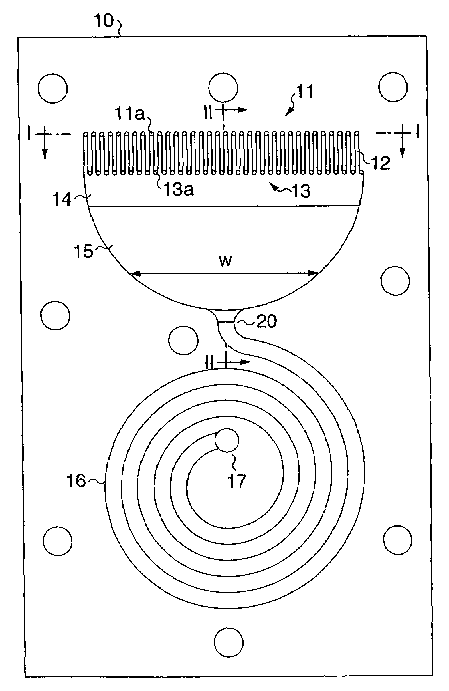
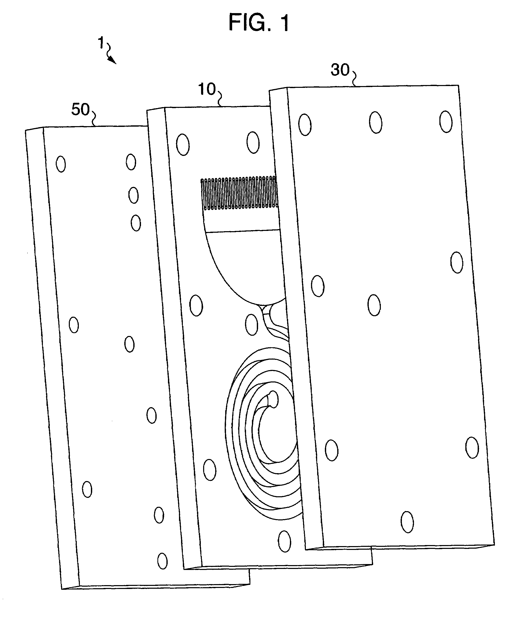
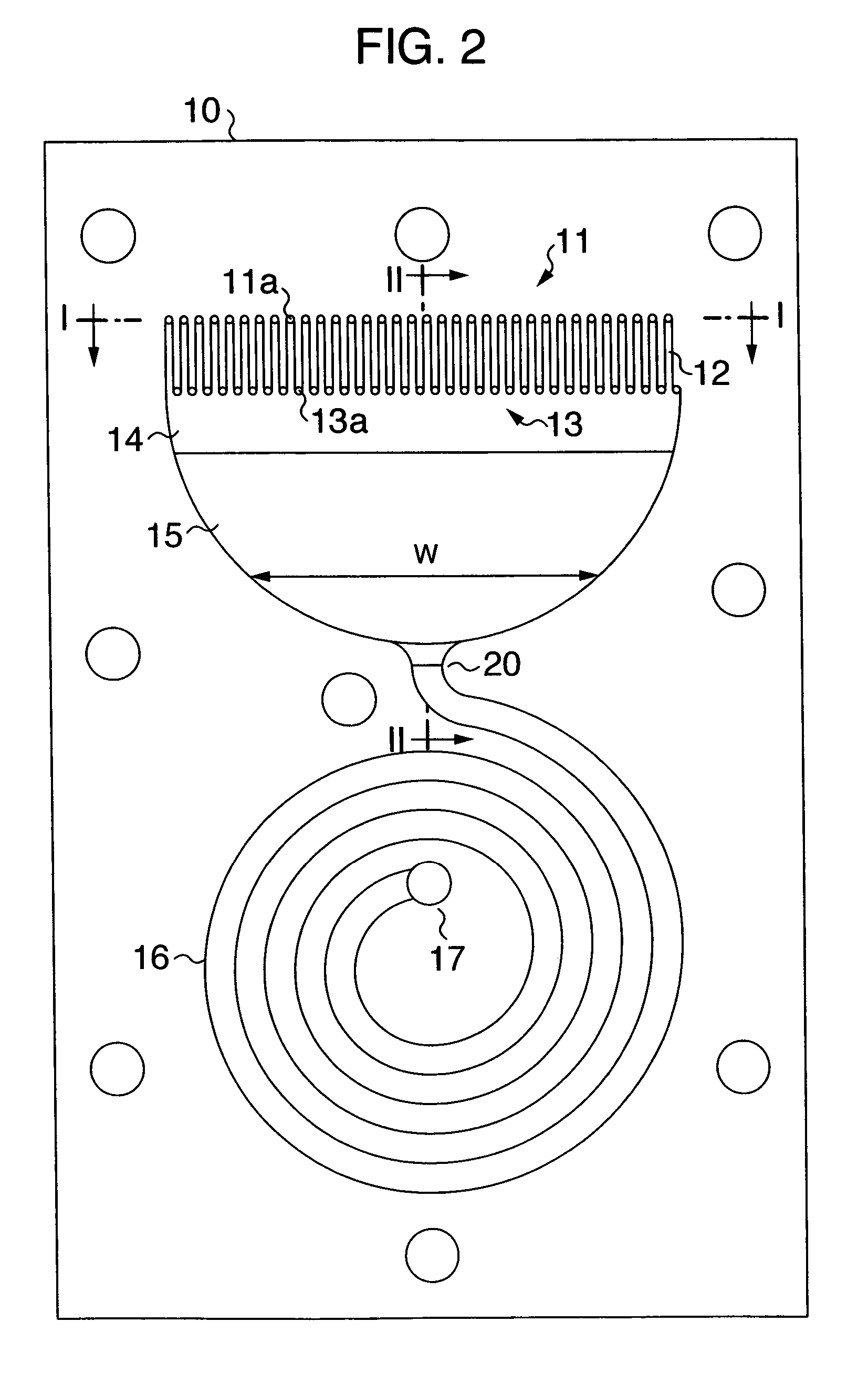
[0044]FIG. 1 is a schematic, exploded, perspective view showing a whole micro fluid chip 1.

[0045]The micro fluid chip 1 comprises a micro fluid chip body 10 formed from a plate, which is made of metal, glass, silicone, resin, etc. according to kinds of liquids being subjected to processing such as mixing, reaction, or the like and has a thickness of several mm, a lid member 30 arranged on one main surface of the micro fluid chip body 10 to constitute a roof portion of flow passages in the micro fluid chip body 10, an adapter member 50 arranged on another main surface of the micro fluid chip body 10 opposed to the lid member 30 to couple a liquid feed mechanism such as a pump, etc. to the chip, and sealing members 70, ...


PUM


Abstract

The invention relates to a micro fluid chip that leads liquids supplied from a plurality of liquid supply ports, respectively, to a minute flow passage, performs mixing and reaction (chemical reaction) of the liquids in the minute flow passage, and obtains a liquid having been processed from a liquid discharge port. A micro fluid chip that leads liquids supplied from a plurality of liquid supply ports, respectively, to a minute flow passage, performs mixing / reaction of the liquids in the minute flow passage, and obtains a liquid having been processed from a liquid discharge port, the micro fluid chip comprising liquid supplies that supply a plurality of flows, which are formed by division of two kinds of liquids, respectively, in an alternate arrangement, and a flow flattening portion provided downstream of the liquid supplies to be configured in flow passage such that liquids alternately arranged are decreased in dimension as they go downstream and increased in dimension in a direction, which intersects the direction of arrangement and a direction of flow, as they go downstream, to be made substantially the same or slightly large in cross sectional area in the direction of flow. According to the invention, liquids of large flow rates can be processed at high speed and an apparatus is not made large in size.

Description

BACKGROUND OF THE INVENTION[0001]The present invention relates to a micro fluid chip that leads liquids supplied from a plurality of liquid supply ports, respectively, to a minute flow passage, performs mixing and reaction (chemical reaction) of the liquids in the minute flow passage, and gets a processed liquid from a liquid discharge port.[0002]A micro fluid chip is an apparatus that supplies a plurality of liquids to a minute flow passage having a width of and a depth of several μm to several hundreds μm and performs mixing and reaction of the liquids in the minute flow passage on the basis of the spontaneous behavior of molecules and particles, which constitute the liquids.[0003]That is, the Reynolds number of liquids amounts to several hundreds or less in a minute flow passage provided in a micro fluid chip, and thus laminar flow becomes dominant unlike conventional reaction apparatuses, in which turbulent flow is dominant. Mixing / reaction of liquids under the domination of lam...

Claims


Application Information

Patent Timeline
Patent Type & Authority Patents(United States)
IPC IPC(8): B01J19/26B01J19/00
CPCB01F5/0451B01F5/0453B01F5/0456B01F5/0646B01F5/0647B01F13/0062B01F13/0066B01J19/0093B81B1/00B01J2219/00783B01J2219/00889B01J2219/00891B81B2201/051B01F25/3132B01F25/31322B01F25/3131B01F25/4331B01F25/433B01F33/3011B01F33/3012
Inventor ITO, YUZURUENDO, YOSHISHIGEKOIDE, AKIRA
Owner HITACHI LTD
Why Eureka
Try Eureka