Steering and suspension system for a vehicle

a steering and suspension system technology, applied in suspensions, resilient suspensions, vehicle components, etc., can solve the problems of increasing the load affecting the stability so as to reduce the impact isolation of the road profile, reduce the impact of the steering system, and improve the effect of traction steering concerns that may arise during combined acceleration and turn events

Active Publication Date: 2009-02-17
GM GLOBAL TECH OPERATIONS LLC
View PDF6 Cites 17 Cited by
  • Summary
  • Abstract
  • Description
  • Claims
  • Application Information

AI Technical Summary

Benefits of technology

[0010]An advantage of an embodiment of the present invention is that, with a relatively short spindle length, traction steer concerns that may arise during combined acceleration and turn events are minimized. Also, road profile impact isolation may be improved and high speed shake due to rotating assembly imbalances may be reduced. And, with a reduced steer axis inclination, the camber angle of the tire on the outside of a turn may be improved, which in turn, may increase the lateral force generation.
[0011]Another advantage of an embodiment of the present invention is that the steering and suspension system can generally be employed with a vehicle having a frame or body that is configured to accept a conventional McPherson strut-type suspension. The interchangeability of the steering and suspension system with a McPherson strut suspension system minimizes the costs associated with providing the option of a higher performance suspension for an existing vehicle. Moreover, this lends itself to providing different modular assemblies at a vehicle assembly plant, which allows both the steering and suspension system of the present invention and a conventional McPherson strut suspension to be selectively assembled to different vehicles coming down the same assembly line. In particular, the various components can be assembled into the same types of subassemblies and then assembled to the vehicle in essentially the same way as with a conventional McPherson strut suspension.
[0012]An additional advantage of an embodiment of the present invention is that, since the steer axis is now independent of the upper strut mount location, the system design can be adjusted for caster, king pin inclination (KPI), spindle offset, scrub and spindle length without requiring the alteration of the vehicle frame or body. This provides significant adjustability to tune the suspension and steering to have the most desirable qualities for the particular vehicle. Moreover, the steering and suspension system of the present invention allows for easier assembly by being able to accept misalignment and tolerances of components, while still being able to assemble the components together.
[0013]A further advantage of an embodiment of the present invention is that upper and lower attachment joints connecting the strut extension member to the steering knuckle and the strut extension member attachment to the lower control arm are configured to provide durability of the components over the life of the vehicle, while still allowing for tuning the suspension and steering system to provide the desired handling characteristics.

Problems solved by technology

This large spindle axis undesirably increases steering system loads when tractive forces (front wheel drive), road profile impact forces, or rotating assembly imbalance forces are applied.
This undesirable increase in steering system loads is particularly noticeable on front wheel drive vehicles with high-powered engines.
On these types of vehicles, traction steer concerns may become apparent during combined acceleration and turn events.
While a different type of suspension may be provided for such high-powered vehicles, this may require substantial changes to the vehicle's frame or body to accommodate this different suspension.
The cost to make these changes on an existing vehicle may be prohibitive, leaving one only the choice of the conventional suspension.
While the steering axis may change, these designs have had undesirable drawbacks.
For some, the design of the modified steering and suspension system is much more complicated, costly and / or much heavier than is desirable.
For others, the design may have less than desirable durability characteristics, or be more limited in the types and amount of adjustments that can be made to tune the suspension to its most desirable performance characteristics.

Method used


Image

  • Steering and suspension system for a vehicle
  • Steering and suspension system for a vehicle
  • Steering and suspension system for a vehicle

Examples


first embodiment

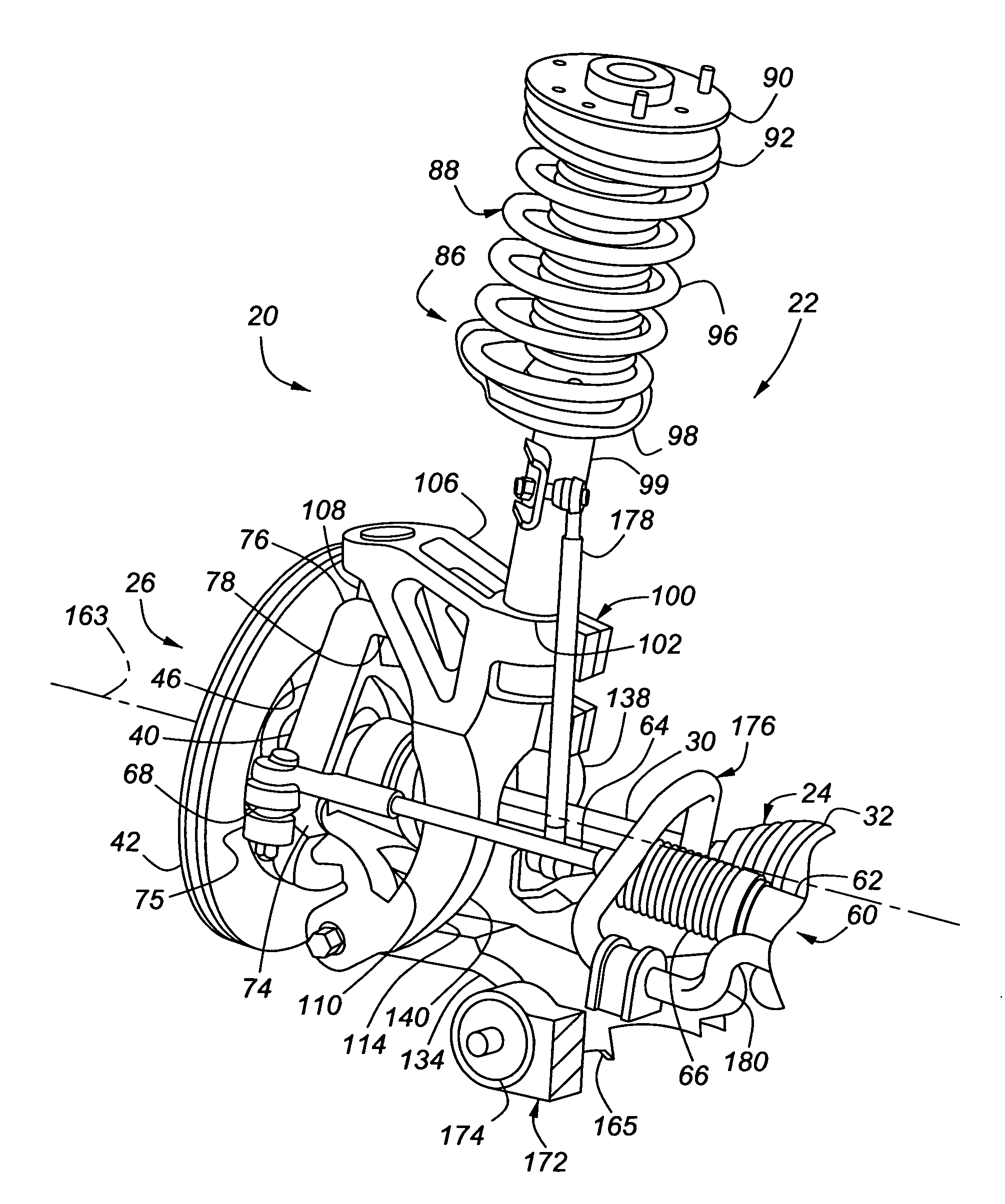
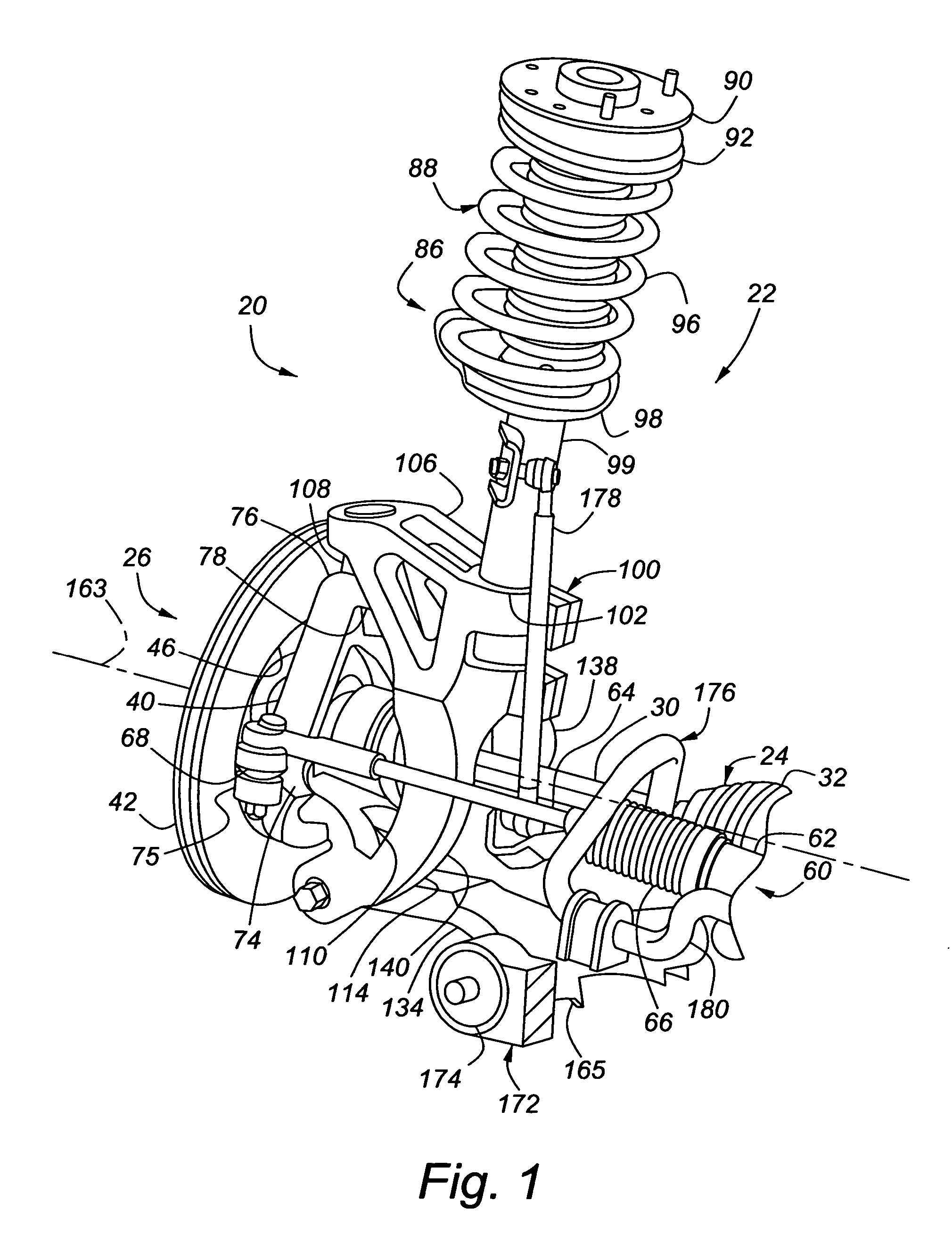
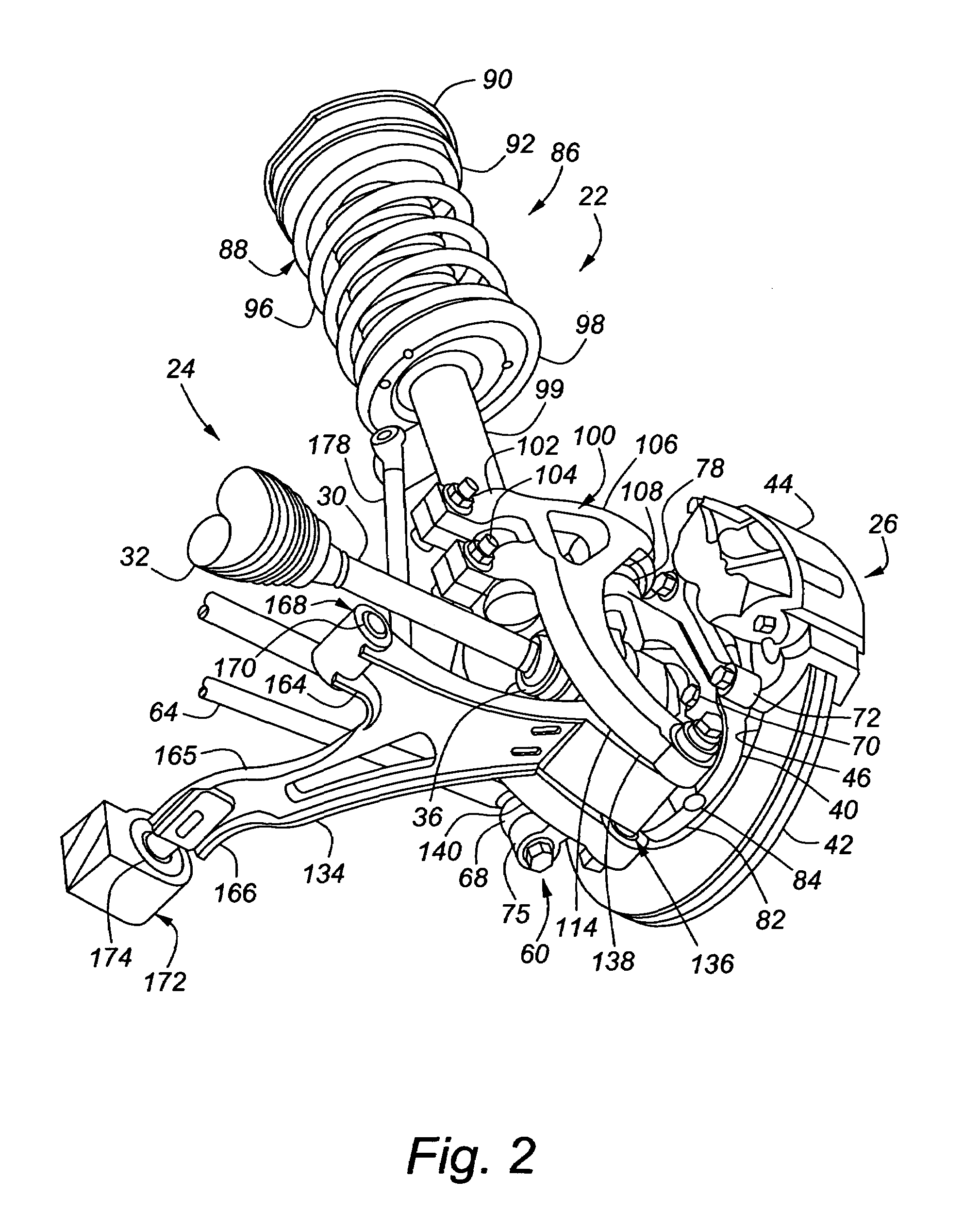
[0024]Referring now to FIGS. 1-8, which illustrate the present invention, a portion of steering and suspension system 22, as would be employed on a front left corner of a vehicle 20, are shown. While these figures only illustrate the front left portion, the front right portion is essentially the same and so will not be illustrated herein. The steering and suspension system 22 cooperates with a driveline system, indicated generally at 24, a braking system, indicated generally at 26, and a wheel and tire assembly, indicated generally at 28.

[0025]The driveline system 24 includes a half shaft 30 connected at an inboard end to a transaxle (not shown) via a first constant velocity (CV) universal joint 32. An outboard end of the half shaft 30 connects to a drive axle 34 via a second CV joint 36. Wheel bearings 35 mount about a wheel hub 38 that surrounds the drive axle 34 and allow the half shaft 30 to cause the wheel hub 38 and wheel and tire assembly 28 to rotate relative to the suspensi...

second embodiment

[0039]Referring now to FIG. 9, a compliant hinge joint 236 in accordance with the present invention is shown. In this embodiment, the compliant hinge joint 236 connecting the two arms 238, 240 of the extension fork 214 to the lower control arm 234 is made up of two spaced apart bushings 242, 246, rather than one bushing and one ball joint. A forward thrust washer 252 is mounted about the pivot bolt 258 between the forward arm 238 of the extension fork 214 and the lower control arm 234, and a rear thrust washer 256 is mounted about the pivot bolt 258 between the rearward arm 240 of the extension fork 214 and the lower control arm 234. As an option, the thrust washers 252, 256 can be formed integral with the lower control arm 234, if so desired. Also, optionally, there may be an additional thrust washer (not shown) on the forward side of the bushing 246 and / or an additional thrust washer (not shown) on the rear side of the bushing 242, in order to distribute the load transfer at braki...

third embodiment

[0041]Referring now to FIG. 10, a lower joint assembly 312 between the lower support arms 310 of the strut extension member 300 and the lower arm 382 of the steering knuckle 340 in accordance with the present invention is shown. In this embodiment, the lower support arms 310 extend into a cavity 383 in the lower arm 382, with a ball joint portion 328 of the lower joint assembly 312 secured in a through-hole 324 in the lower support arms 310. The pin 330 of the rotating joint portion 326 extends through receptacles 384 in the lower arm 382, which are both above and below the lower support arms 310, as well as extending through the ball joint portion 328.


PUM


Abstract

The present invention concerns a steering and suspension system of a vehicle. The system may include a strut extension member having a strut clamp arm mounted to a strut assembly, an upper extension support arm extending from the strut clamp arm, an extension fork with first and second arms extending from the strut clamp arm, and a lower extension support arm extending from the extension fork. Also, a steering knuckle has an upper portion pivotally coupled to the upper extension support arm, and a lower portion pivotally coupled to the lower extension support arm. A lower control arm has an outboard portion with a control arm mounting bore therethrough, and a compliant hinge joint includes a first joint associated with the first arm, a second joint associated with the second arm, and a shaft extending through the first joint, the second joint and the mounting bore.

Description

BACKGROUND OF INVENTION[0001]The present invention relates generally to vehicle steering and suspension systems and, in particular, to strut-type vehicle steering and suspension systems.[0002]Many automotive vehicles today employ a type of front suspension commonly known as a McPherson strut suspension. This type of suspension includes a strut assembly, with an upper strut mount affixed to a vehicle frame or body and a lower end affixed to a steering knuckle. The lower end of the steering knuckle also attaches, via a ball joint, to a lower control arm, which is hinged to the vehicle frame or body. While this conventional suspension works well for many vehicle applications, it creates a spindle length—the distance from the wheel center plane to steer axis along the wheel rotation axis—that is larger than desirable. The steer axis is located away from the wheel center plane due to the fact that, with this suspension, it is defined by the ball joint and upper strut mount location. This...

Claims


Application Information

Patent Timeline
Patent Type & Authority Patents(United States)
IPC IPC(8): B62D7/18
CPCB60G3/265B60G15/07B62D7/18B60G2200/142B60G2200/17B60G2204/416B60G2206/121B60G3/06B60G2200/44B60G2200/42
Inventor LUTTINEN, JAMES L.SIEBENEICK, JUERGEN W.
Owner GM GLOBAL TECH OPERATIONS LLC
Why Eureka
Try Eureka