Check patentability & draft patents in minutes with Patsnap Eureka AI!

Systems for reverse bias trim operations in non-volatile memory

a technology of non-volatile memory and reverse bias trim, which is applied in the field of integrated circuits containing non-volatile memory cell arrays, can solve problems such as self-limiting operations

Active Publication Date: 2009-02-17
SANDISK TECH LLC
View PDF93 Cites 20 Cited by
  • Summary
  • Abstract
  • Description
  • Claims
  • Application Information

AI Technical Summary

Benefits of technology

The patent describes a method and system for trimming the reset state of non-volatile memory cells. By applying a reverse bias trim voltage to a subset of memory cells that have a resistance beyond a target level, the method and system can lower the resistance of those cells back toward the set level and out of their deeply reset condition. This operation is self-limiting in that cells stop their resistance shifts upon reaching the target level. The technical effect of the patent is to improve the accuracy and reliability of non-volatile memory systems.

Problems solved by technology

The operation is self-limiting in that cells stop their resistance shifts upon reaching the target level.

Method used


Image

  • Systems for reverse bias trim operations in non-volatile memory
  • Systems for reverse bias trim operations in non-volatile memory
  • Systems for reverse bias trim operations in non-volatile memory

Examples


Embodiment Construction

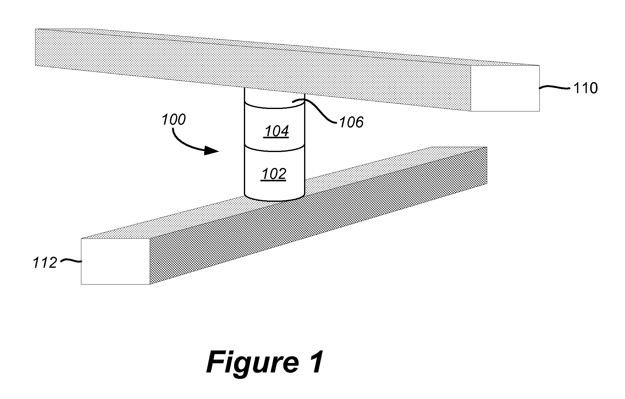
[0049]FIG. 1 depicts an exemplary structure for a non-volatile memory cell that can be used in accordance with embodiments of the present disclosure. A two-terminal memory cell 100 as depicted in FIG. 1 includes a first terminal portion connected to a first conductor 110 and a second terminal portion connected to a second conductor 112. The memory cell includes a steering element 102 in series with a state change element 104 and an anti-fuse 106 to provide non-volatile date storage. The steering element can take the form of any suitable device exhibiting a nonlinear conduction current characteristic such as a simple diode. The state change element will vary by embodiment and can include numerous types of materials to store data through representative physical states. State change element 104 can include resistance change materials, phase change resistive materials, etc. For example, a semiconductor or other material having at least two levels of detectable resistance change (e.g., l...


PUM


Abstract

A reverse bias trim operation for the reset state of a non-volatile memory system is disclosed. Non-volatile memory cells including a resistance change element undergo a reverse bias reset operation to change their resistance from a set state at a first level of resistance to a reset state at a second level of resistance. Certain memory cells in a set of cells that was reset may be deeply reset to a level of resistance beyond a target level for the reset state. A second reverse bias is applied to the set of memory cells to move the resistance of each cell that was deeply reset toward the target level of the reset state. A smaller reverse bias than used for the reset operation can shift the resistance of the cells back toward the set level and out of their deeply reset condition. The operation is self-limiting in that cells stop their resistance shifts upon reaching the target level. Cells that were not deeply reset are not affected.

Description

CROSS-REFERENCE TO RELATED APPLICATIONS[0001]The following related applications, filed on even date herewith, are cross-referenced and incorporated by reference herein in their entirety:[0002]U.S. patent application Ser. No. 11 / 461,393, entitled “Controlled Pulse Operations in Non-Volatile Memory,” filed concurrently;[0003]U.S. patent application Ser. No. 11 / 461,399, entitled “Systems for Controlled Pulse Operations in Non-Volatile Memory,” filed concurrently;[0004]U.S. patent application Ser. No. 11 / 461,410, entitled “High Bandwidth One Time Field-Programmable Memory,” by Roy E. Scheuerlein and Christopher J. Petti;[0005]U.S. patent application Ser. No. 11 / 461,419, entitled “Systems For High Bandwidth One Time Field-Programmable Memory,” by Roy E. Scheuerlein and Christopher J. Petti;[0006]U.S. patent application Ser. No. 11 / 461,424, entitled “Reverse Bias Trim Operations in Non-Volatile Memory,” by Roy E. Scheuerlein and Tanmay Kumar;[0007]U.S. patent application Ser. No. 11 / 496,9...

Claims


Application Information

Patent Timeline
Patent Type & Authority Patents(United States)
IPC IPC(8): G11C13/04
CPCG11C5/02G11C8/08G11C11/56G11C13/0023G11C13/0028G11C13/0038G11C13/0069G11C13/0097G11C17/16G11C17/18G11C2213/71G11C2213/72
Inventor SCHEUERLEIN, ROY E.KUMAR, TANMAY
Owner SANDISK TECH LLC
Features
  • R&D
  • Intellectual Property
  • Life Sciences
  • Materials
  • Tech Scout
  • Unparalleled Data Quality
  • Higher Quality Content
  • 60% Fewer Hallucinations
Learn More