
Fuel supply system for diesel engine

a fuel supply system and diesel engine technology, applied in the direction of fuel injecting pumps, electric control, machines/engines, etc., can solve the problems of increasing the weight of the fuel line system, increasing the quantity of fuel returned from the high-pressure fuel pump, and deteriorating the accuracy of controlling the injection quantity of fuel, so as to suppress the thermal influence of the component parts of the fuel tank

Inactive Publication Date: 2009-02-24
HONDA MOTOR CO LTD
View PDF47 Cites 22 Cited by
  • Summary
  • Abstract
  • Description
  • Claims
  • Application Information

AI Technical Summary

Benefits of technology

The system reduces the flow rate of feed fuel during idling or low / high temperatures, preventing filter clogging and thermal damage, resulting in a lightweight fuel line system with improved injection quantity control and extended component durability.

Problems solved by technology

If the low-pressure fuel pump supplies the fuel at a fixed fuel supply rate to the high-pressure fuel pump, the fuel is supplied excessively to the high-pressure fuel pump during idling operation in which the injection quantity is small and, consequently, the quantity of the fuel returned from the high-pressure fuel pump increases.
If a return fuel pipe connected to the high-pressure fuel pump is used also as a return fuel pipe connected to the fuel injection valves and the pressure fuel accumulator, a large quantity of the fuel that has returned from the high-pressure fuel pump, in some cases, obstructs the smooth flow of the fuel returned from the fuel injection valves and the pressure fuel accumulator and causes troubles including the deterioration of the accuracy of controlling the injection quantity of the fuel.
The weight of a fuel line system increases and the piping of the fuel line system is complicated when a fuel return pipe of a large diameter is used and fuel return pipes are connected individually to the fuel injection valves and the pressure fuel accumulator to return the fuel smoothly.
Consequently, it is possible that the fuel filter is clogged up with the wax and the fuel cannot be supplied at a predetermined rate when a large quantity of the fuel flows through the fuel filter.
If a large quantity of the fuel heated at a high temperature is returned into the fuel tank after the high-load operation of the engine, component parts of the fuel tank including rubber seals are exposed to heat, which affects the life of those component parts adversely.
However, the return fuel is not cooled by running wind while the vehicle is stopping and the engine is in an idling state, the effect of the high-temperature return fuel on the component parts of the fuel tank is significant.

Method used


Image

  • Fuel supply system for diesel engine
  • Fuel supply system for diesel engine
  • Fuel supply system for diesel engine

Examples


Embodiment Construction

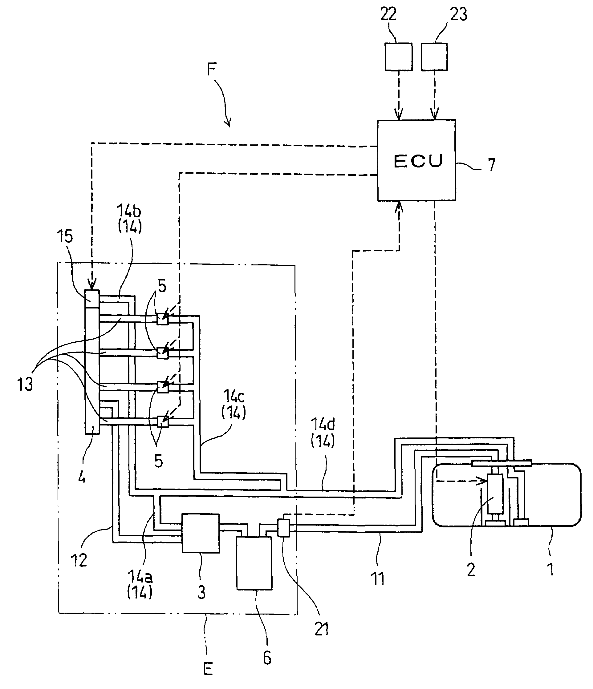
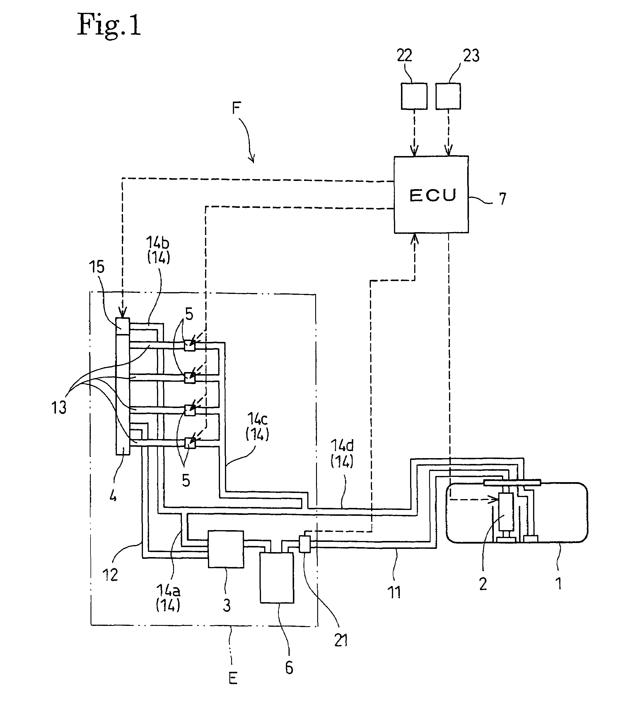
[0021]Referring to FIG. 1, a fuel supply system F in a preferred embodiment of the present invention is intended to be used for a diesel engine E. The diesel engine E is an automotive in-line 4-cylinder 4-stroke engine mounted on a vehicle. The diesel engine E has an engine body including a cylinder block provided with cylinders in which pistons reciprocates to drive a crankshaft for rotation, and a cylinder head. Fuel injection valves 5 are attached to the cylinder head. The fuel injection valves 5 inject fuel directly into combustion chambers each formed between the cylinder head and the piston.

[0022]The fuel supply system F supplies the fuel, light oil, to be injected into the combustion chambers, to the fuel injection valves 5. The fuel supply system F includes a fuel tank 1 made of a synthetic resin and containing the fuel, a low-pressure pump 2 which pumps up the fuel from the fuel tank 1 and forces the fuel out as feed fuel, a high-pressure fuel pump 3 which sucks the feed fu...


PUM


Abstract

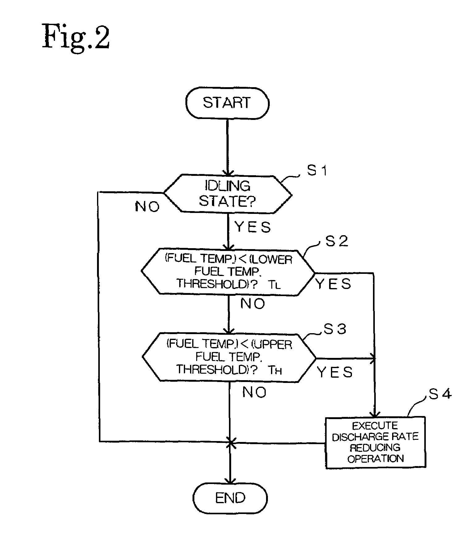
A fuel supply system is incorporated into a diesel engine including a low-pressure fuel pump 2, a high-pressure fuel pump 3, a common rail 4, fuel injection valves 5 and a fuel return line 14. The fuel supply system reduces the discharge rate of the low-pressure fuel pump 2 supplying the fuel to the high-pressure fuel pump 3 when the diesel engine is in an idling state and the temperature of the fuel is below a lower fuel temperature threshold and when the diesel engine is in an idling state and the temperature of the fuel is above an upper fuel temperature threshold. The flow rate of the feed fuel discharged from the low-pressure fuel pump is reduced when an idling state or a specific state where the fuel is at a specific temperature. Thus the fuel line system of the fuel supply system can be built in a lightweight arrangement and the piping of the fuel line system can be simplified.

Description

BACKGROUND OF THE INVENTION[0001]1. Technical Field[0002]The present invention relates to a fuel supply system for a diesel engine provided with a pressure fuel accumulator and, more specifically, to a fuel supply system capable of controlling the discharge of a low-pressure fuel pump for supplying fuel to a high-pressure fuel pump.[0003]2. Description of the Related Art[0004]A diesel engine provided with a pressure fuel accumulator for accumulating fuel discharged from a high-pressure fuel pump under pressure, such as disclosed in JP-A 2003-176761, is well known. Generally, in a diesel engine provided with a pressure fuel accumulator, injection quantity of the fuel to be injected in each injection cycle of a fuel injection valve is controlled through the control of injection valve opening duration. Therefore a low pressure fuel pump for supplying the fuel to a high-pressure fuel pump is operated at a fixed discharge rate to adjust the pressure of the fuel in the pressure fuel accum...

Claims


Application Information

Patent Timeline
Patent Type & Authority Patents(United States)
IPC IPC(8): F02M37/04F02D41/38
CPCF02D33/006F02D41/3854F02M59/34F02M63/023F02M63/025F02B3/06F02D41/08F02D41/3082F02D2200/0606F02M37/0052F02M37/10F02M63/0225
Inventor FUNABASHI, MAMORUEBINUMA, YUTA
Owner HONDA MOTOR CO LTD
Learn More