Phase-locked loop using multi-phase feedback signals

a feedback signal and multi-phase technology, applied in the field of phase-locked loops, can solve the problems of interference with the operation of surrounding equipment, fractional spurs that are worse for small or large values of k/f, and larger fractional spurs

Inactive Publication Date: 2009-02-24
AVAGO TECH INT SALES PTE LTD
View PDF2 Cites 35 Cited by
  • Summary
  • Abstract
  • Description
  • Claims
  • Application Information

AI Technical Summary

Problems solved by technology

However, at such high frequencies, these digital circuits may radiate signals as electromagnetic energy, and these electromagnetic emissions may interfere with the operation of surrounding equipment.
One drawback to this technique is that feedback divider 110 will jump from N to N+1 whenever accumulator 112 generates consecutive carry-out values Cout of 0 and 1, respectively.
Another drawback to this technique is that the fractional spur is worse for small or large values of K / F (i.e., close to 0 or close to 1, respectively) than for intermediate values (i.e., close to ½).
In these cases, loop filter 106 having a fixed loop bandwidth is less effective at filtering out the periodic phase hit, resulting in larger fractional spurs.
One drawback to this technique is that the fractional resolution of the PLL is limited based on the number of output signals generated by the VCO.

Method used


Image

  • Phase-locked loop using multi-phase feedback signals
  • Phase-locked loop using multi-phase feedback signals
  • Phase-locked loop using multi-phase feedback signals

Examples


Embodiment Construction

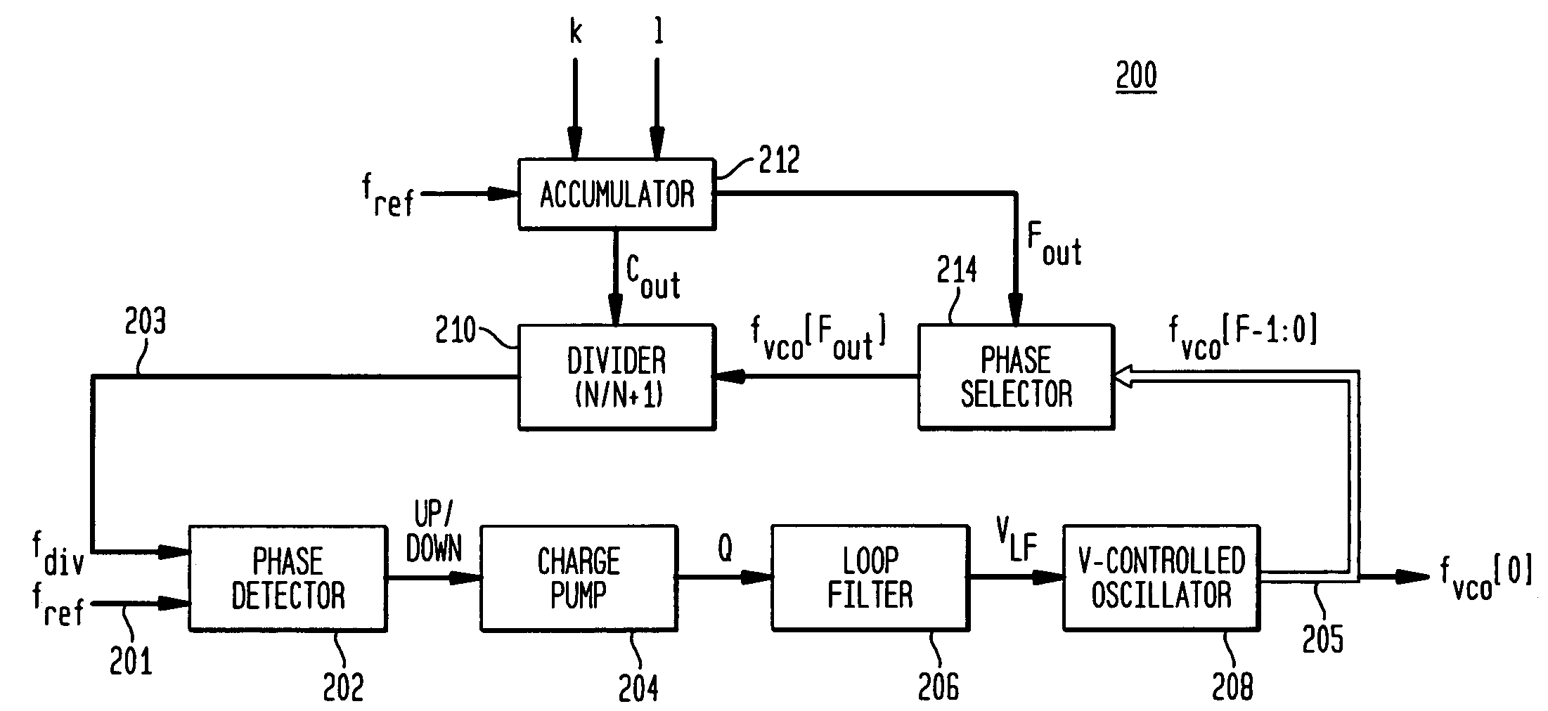
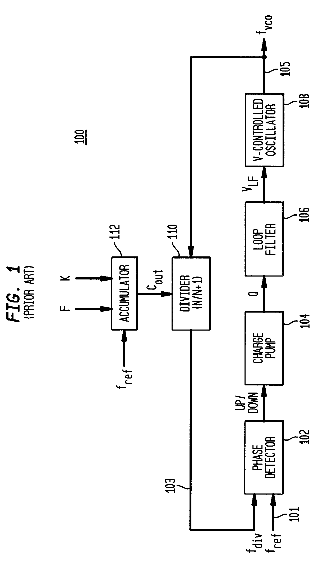
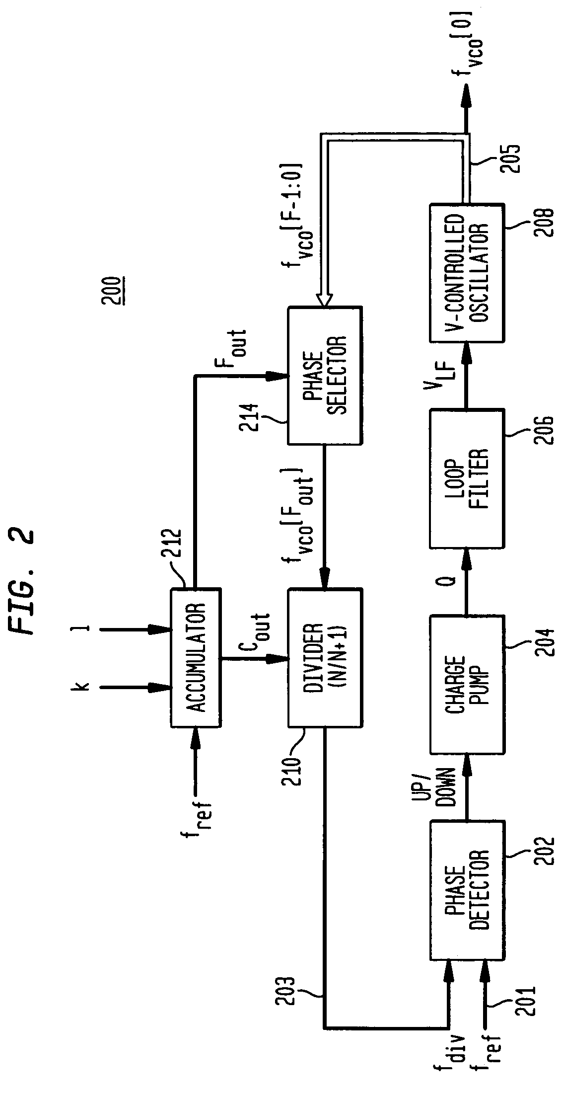
[0020]FIG. 2 shows a block diagram of an exemplary embodiment of a fractional-N PLL 200. PLL 200 has a main signal path consisting of PD 202, charge pump 204, loop filter 206, and VCO 208 and a feedback signal path consisting of phase selector 214 and feedback divider 210 controlled by fractional accumulator 212. PD 202, charge pump 204, loop filter 206, VCO 208, feedback divider 210, and fractional accumulator 212 of PLL 200 are analogous to corresponding elements in PLL 100 of FIG. 1. In fact, PD 202, charge pump 204, loop filter 206, and feedback divider 210 may be identical to the corresponding elements in FIG. 1. The differences between PLL 200 of FIG. 2 and PLL 100 of FIG. 1 lie in the operations of VCO 208 and fractional accumulator 212 and the existence of phase selector 214.

[0021]Unlike VCO 108 of FIG. 1, which generates a single VCO output signal 105 whose frequency fvco is a function of the applied loop-filter voltage, VCO 208 of FIG. 2 generates F VCO output signals 205,...


PUM


Abstract

A signal generator, such as a fractional-N PLL, has, in its feedback signal path, a divider, a phase circuit, and a fractional accumulator that generates control signals for the divider and the phase circuit. The divider control signal controls the divisor value applied by the divider. In one embodiment, a phase selector selects, based on the phase-circuit control signal, one of a plurality of phase-shifted output signals generated by the PLL's main signal path (e.g., by a multi-phase VCO) and the divider generates the feedback signal for the PLL from the selected signal. In another embodiment, the divider generates a divided signal from one of the phase-shifted output signals, and a phase mixer generates, from the divided signal, a plurality of phase-shifted divided signals and selects, based on the phase-circuit signal, one of the phase-shifted divided signals as the PLL's feedback signal.

Description

BACKGROUND OF THE INVENTION[0001]1. Field of the Invention[0002]The present invention relates to electronic circuits, and, in particular, to signal generators, such as phase-locked loops.[0003]2. Description of the Related Art[0004]In many electronics applications, digital circuits are employed that operate with one or more clock signals. Personal computers commonly employ a processor that may operate based on a clock having a frequency of 350 MHz, and 1 GHz frequencies are becoming common. However, at such high frequencies, these digital circuits may radiate signals as electromagnetic energy, and these electromagnetic emissions may interfere with the operation of surrounding equipment. Since these emissions are based upon clock signals, high emitted energy “spikes” occur at these clock signal frequencies and their harmonics. Consequently, equipment is often shielded to prevent or minimize these emissions within certain frequency ranges, or operation is modified to spread the emitte...

Claims


Application Information

Patent Timeline
Patent Type & Authority Patents(United States)
IPC IPC(8): H03D3/24
CPCH03L7/081H03L7/1976
Inventor LEONOWICH, ROBERT H.ZHUANG, ZAILONG
Owner AVAGO TECH INT SALES PTE LTD
Why Eureka
Try Eureka