Independently controlled, double gate nanowire memory cell with self-aligned contacts

a nanowire memory cell, self-aligning technology, applied in the direction of semiconductor devices, electrical equipment, transistors, etc., can solve the problems of requiring a relatively high voltage, 100 volts) for the bias, and the oxide layer is relatively thick

Inactive Publication Date: 2009-03-03
INTEL CORP
View PDF16 Cites 50 Cited by
  • Summary
  • Abstract
  • Description
  • Claims
  • Application Information

AI Technical Summary

Problems solved by technology

Unfortunately, the oxide layer is relatively thick, requiring a relatively high voltage (e.g., 100 volts) for the bias.
These structures are difficult to fabricate.

Method used


Image

  • Independently controlled, double gate nanowire memory cell with self-aligned contacts
  • Independently controlled, double gate nanowire memory cell with self-aligned contacts
  • Independently controlled, double gate nanowire memory cell with self-aligned contacts

Examples


Embodiment Construction

[0025]In the following description, a memory and method for fabricating the memory is described. Numerous specific details are set forth, such as specific conductivity types, and metalization arrangements, to provide a thorough understanding of the present invention. It will be apparent to one skilled in the art, that the present invention may be practiced without these specific details. In other instances, well known processing steps and circuits have not been described in detail, in order not to unnecessarily obscure the present invention.

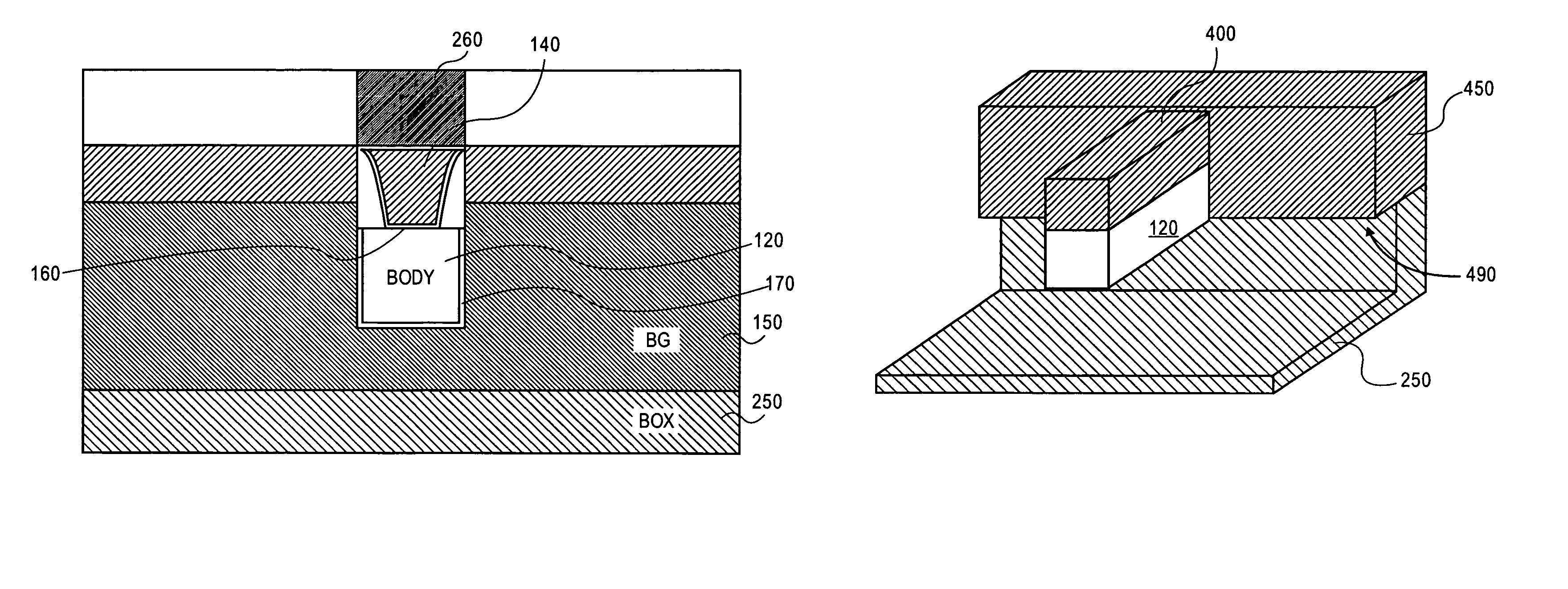
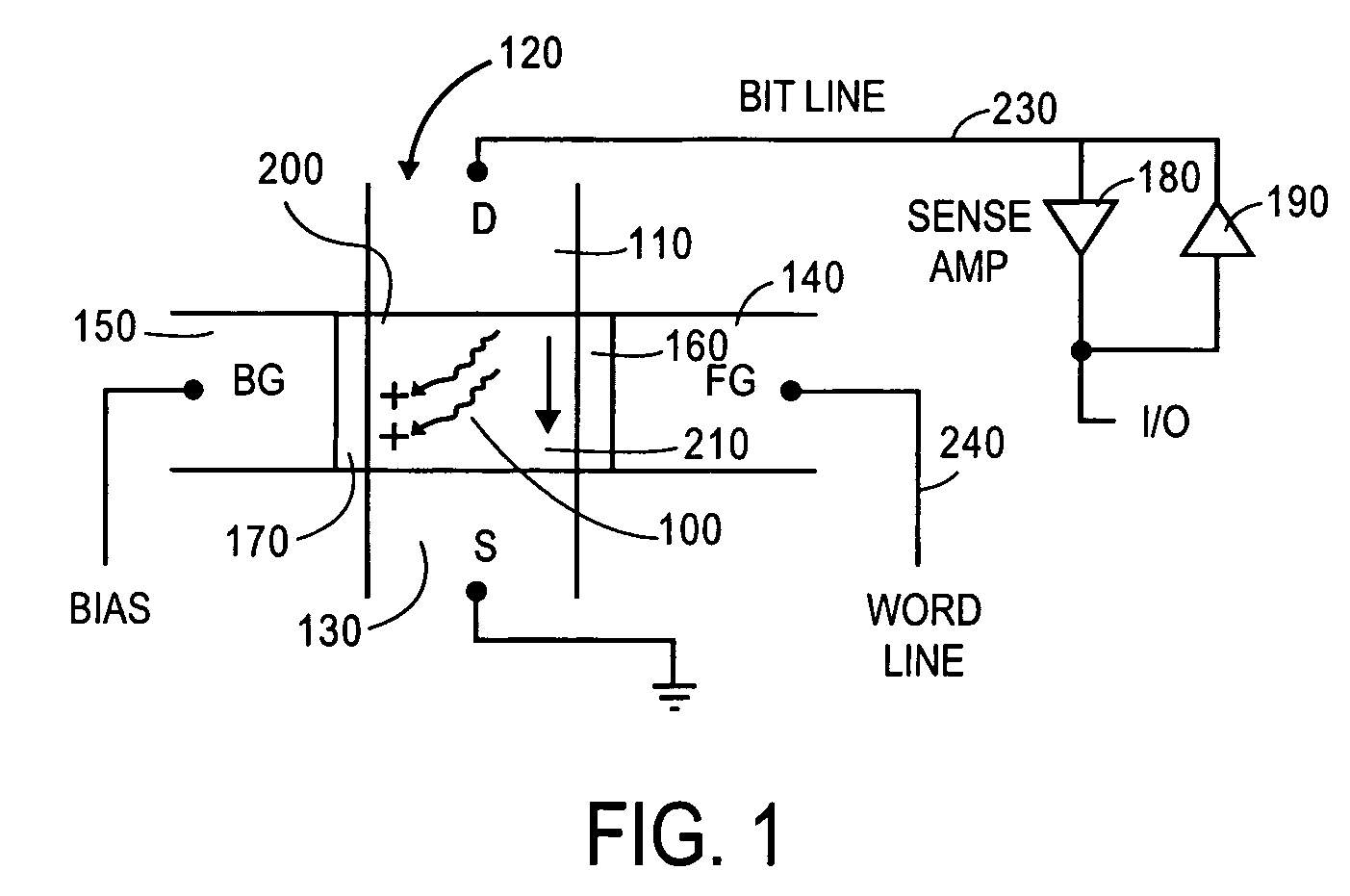
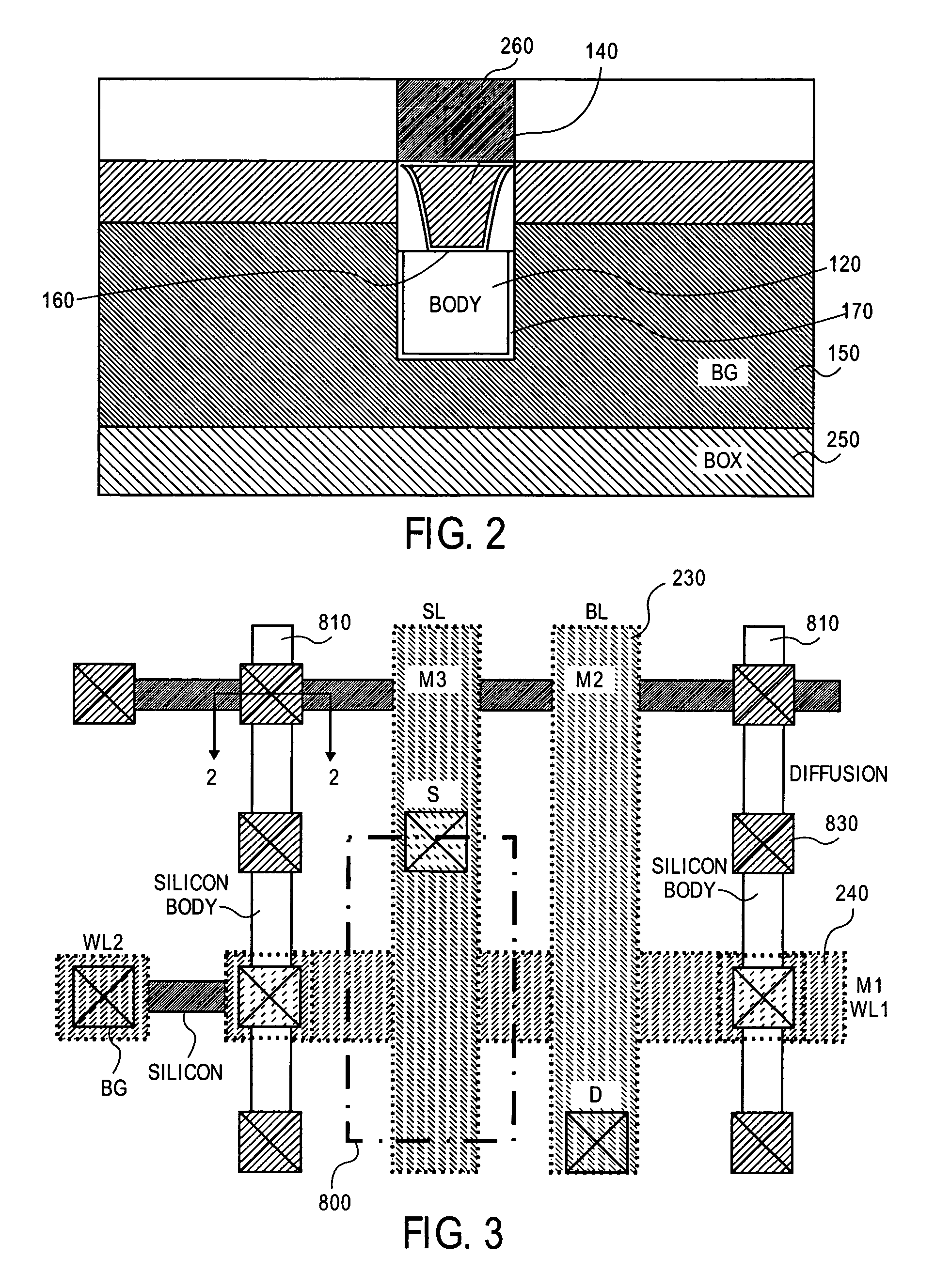
[0026]A single memory cell is shown in schematic form in FIG. 1. A portion of a semiconductor line or body 120, formed on an oxide layer (such as BOX 250 of FIG. 2), and etched from, for example, a monocrystalline silicon layer is illustrated. The body 120 includes a pair of spaced-apart, doped regions 110 and 130, disposed in first opposite sides of the body thereby defining a channel region 100. In one embodiment, the channel region is a p type...


PUM


Abstract

A doubled gate, dynamic storage device and method of fabrication are disclosed. A back (bias gate) surrounds three sides of a semiconductor body with a front gate disposed on the remaining surface. Two different gate insulators and gate materials may be used.

Description

FIELD OF THE INVENTION[0001]This invention relates to the field of dynamic, random-access memories (DRAMs), and devices with double gates, particularly those using transistors with floating bodies.PRIOR ART AND RELATED ART[0002]Most common DRAM cells store charge on a capacitor and use a single transistor for accessing the capacitor. More recently, a cell has been proposed which stores charge in a floating body of a transistor. A back gate is biased to retain charge in the floating body.[0003]In one proposal, an oxide layer is formed on a silicon substrate and a silicon layer for the active devices is formed on the oxide layer (SOI substrate). The silicon substrate is used as the back gate, and consequently, must be biased relative to the silicon layer. Unfortunately, the oxide layer is relatively thick, requiring a relatively high voltage (e.g., 100 volts) for the bias.[0004]Several structures have been proposed to reduce this relatively high bias potential, including use of a doub...

Claims


Application Information

Patent Timeline
Patent Type & Authority Patents(United States)
IPC IPC(8): H01L21/338
CPCH01L21/84H01L27/108H01L27/10802H01L27/10844H01L27/1203H01L29/7841H01L29/0657H10B12/20H10B12/01H10B12/00
Inventor BAN, IBRAHIMCHANG, PETER L. D.
Owner INTEL CORP
Why Eureka
Try Eureka