
Small piezoelectric or electrostrictive linear motor

a piezoelectric or electrostrictive technology, applied in piezoelectric/electrostrictive/magnetostrictive devices, piezoelectric/electrostrictive/magnetostriction machines, piezoelectric/electrostrictive/magnetostriction device details, etc., can solve the problems of high electric current, excessive heat generation, and limited use of small stepping motors. , to achieve the effect of improving the efficiency of the manufacturing process, improving the quality

Active Publication Date: 2009-03-03
PIEZOELECTRIC TECH
View PDF10 Cites 7 Cited by
  • Summary
  • Abstract
  • Description
  • Claims
  • Application Information

AI Technical Summary

Benefits of technology

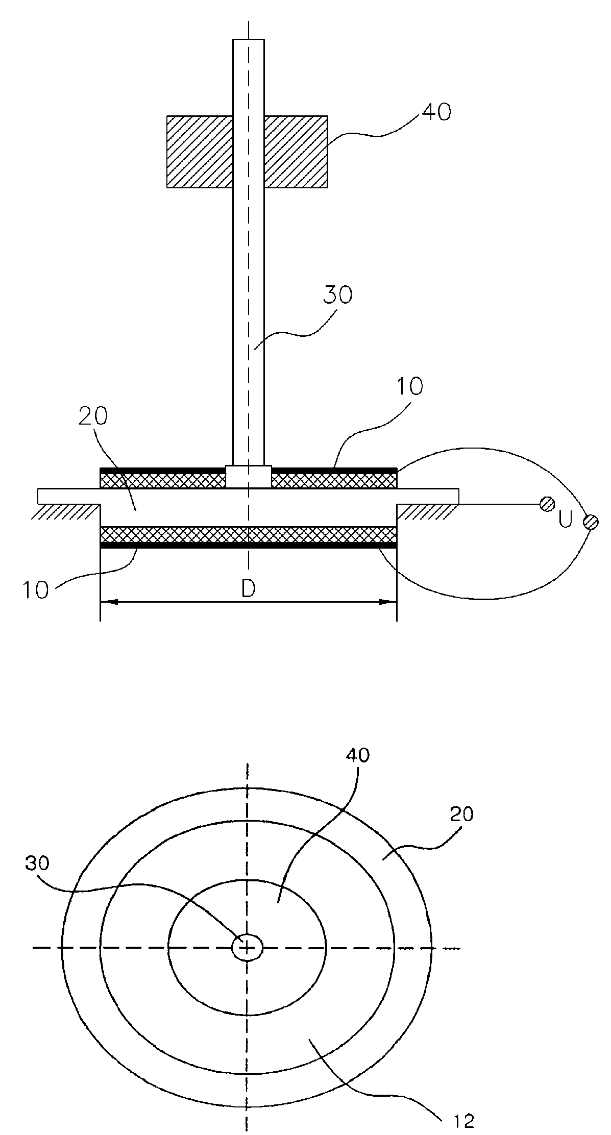
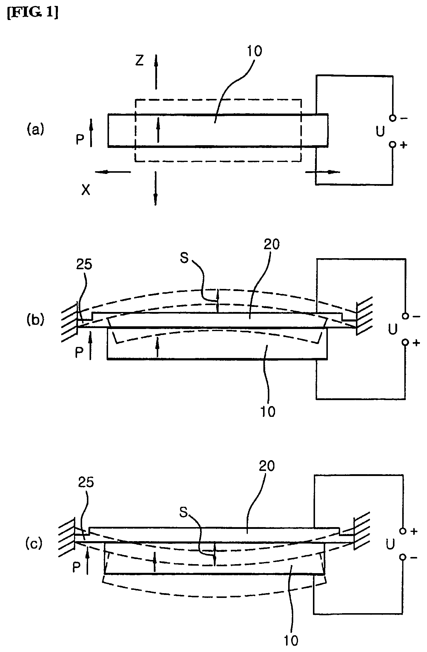
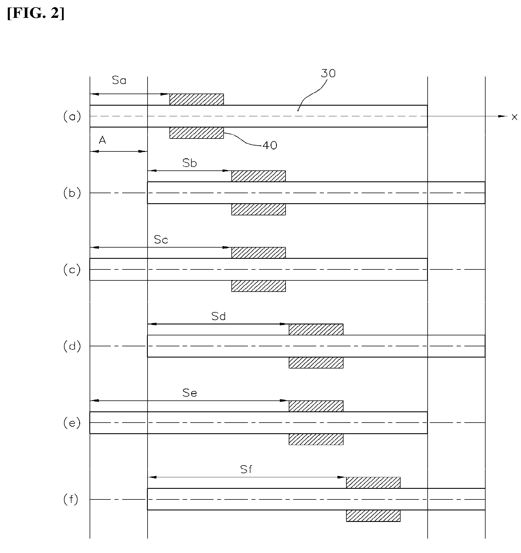
[0028]In the present invention, a small piezoelectric / electrostrictive ultrasonic linear motor having the above-mentioned construction uses bending movement of a unimorph or bimorph including both an elastic body 20 and a piezoelectric or electrostrictive substrate 10 as its driving source, so that a movable body 40 moves along a movable shaft 30. Thus, the present invention provides a small piezoelectric / electrostrictive ultrasonic linear motor which is able to simplify its manufacturing process, and easily practicable according to a basic principle, and has superior characteristics. Furthermore, the small piezoelectric / electrostrictive ultrasonic linear motor is advantageous in that its thrust is superior for its size, operation is speedy, and the drive is stable.

Problems solved by technology

Furthermore, in conventional small stepping motors, when rotated or reversely rotated, backlash occurs, thus resulting in error.
Therefore, such small stepping motors have been limitedly used.
In addition, the small stepping motor is problematic in that high electric current is required and excessive heat is generated.
In the meantime, several other vibration transmitting methods have been proposed, but, because maintaining constant vibration amplitude is difficult due to wear resulting from repeated motion over a long period of time, it is very hard to put into practical use.

Method used


Image

  • Small piezoelectric or electrostrictive linear motor
  • Small piezoelectric or electrostrictive linear motor
  • Small piezoelectric or electrostrictive linear motor

Examples


Embodiment Construction

[0037]In order to accomplish the above object, the present invention provides a fundamental construction which includes a piezoelectric or electrostrictive substrate 10, a movable body 40, a movable shaft 30 and an elastic body 20. Furthermore, in the present invention, various type small piezoelectric / electrostrictive ultrasonic linear motors including linear motors having three kinds of structures, which will be explained in preferred embodiments, are proposed, based on the above-mentioned fundamental construction.

[0038]FIGS. 4, 5 and 6 show three kinds of small piezoelectric / electrostrictive ultrasonic linear motors having the above-mentioned fundamental construction.

[0039]FIG. 4 shows a first embodiment of the present invention which includes a piezoelectric or electrostrictive substrate 10, an elastic body 20 and a movable body 40. The assembly of the piezoelectric or electrostrictive substrate 10 and the elastic body 20 forms a unimorph having a disk shape. The elastic body 20...


PUM


Abstract

The present invention provides a small piezoelectric / electrostrictive ultrasonic linear motors which are installed in cell phones or PDAs, etc. to drive their camera lenses. In the present invention, a movable shaft (30) is coupled to a unimorph or bimorph, which is made by attaching a piezoelectric or electrostrictive substrate to an elastic body (20) (metal), so that a movable body (40) fitted over the movable shaft (30) is linearly moved along the movable shaft (30) by vibration of the piezoelectric or electrostrictive substrate, thus simplifying a manufacturing process, being easily practicable according to a basic principle, and having superior characteristics.

Description

CROSS REFERENCE TO RELATED APPLICATION[0001]This application is a 35 USC § 371 National Phase Entry Application from PCT / KR2005 / 000353, filed Feb. 4, 2005, and designating the United States.TECHNICAL FIELD[0002]The present invention relates, in general, to small piezoelectric / electrostrictive ultrasonic linear motors which are installed in cell phones or PDAs, etc. to drive their camera lenses and, more particularly, to a small piezoelectric / electrostrictive ultrasonic linear motor in which a movable shaft 30 is coupled to a unimorph or bimorph, which is made by attaching a piezoelectric or electrostrictive substrate to an elastic body 20 (metal), so that a movable body 40 fitted over the movable shaft 30 is linearly moved along the movable shaft 30 by vibration of the piezoelectric or electrostrictive substrate, thus simplifying a manufacturing process, and being easily practicable according to a basic principle, and having a superior characteristic.BACKGROUND ART[0003]Small steppi...

Claims


Application Information

Patent Timeline
Patent Type & Authority Patents(United States)
IPC IPC(8): H01L41/04H01L41/09H02N2/04
CPCH02N2/025H01L41/0973H10N30/2047
Inventor PIOTR, VASILJEFKIM, BO KEUNYOON, SEOK MINYOON, SEONG YIL
Owner PIEZOELECTRIC TECH
Learn More