Electrographic position location apparatus and method

a position location and electromechanical technology, applied in static indicating devices, instruments, differential interacting antenna combinations, etc., can solve the problems of large number of pixel elements required to achieve a high resolution, limited resolution of conventional membrane switches, and significant electronic memory and computing time for mathematical calculations. achieve the effect of improving linearity, reducing curvature, and improving the control of equipotential contours

Inactive Publication Date: 2009-03-03
LEAPFROG ENTERPRISES
View PDF55 Cites 23 Cited by
  • Summary
  • Abstract
  • Description
  • Claims
  • Application Information

AI Technical Summary

Benefits of technology

[0016]The novel and inventive antenna apparatus described herein can radiate a two dimensional electric field potential that can be properly described by set of vertical or horizontal equipotential field lines, each line having a different potential value associated with it. The magnitude and gradient of the radiated field lines is easily designed into the antenna apparatus. Because the generated field potential is easily calculated as a function of the antenna design, it can be used to locate which line a receiving antenna lies on. As a receiving antenna is moved from one equipotential line to another, it will pick up the field strength of the line over which it is located. If the receiving antenna is placed in a single location over the radiating (or transmitting) antenna, the magnitude of the potential the antenna senses will reveal on which equipotential line the receiving antenna is located.
[0020]One object of the present invention is to provide an antenna apparatus for electrographic system with improved control of the equipotential contours. A specific object is to reduce curvature, improve linearity and improve orthogonality of the equipotential contours. In a preferred embodiment, the fingers of the first antenna are oriented in localized regions in a direction generally orthogonal to the fingers of the second antenna.

Problems solved by technology

However, conventional membrane switches have limited resolution.
However, a disadvantage of this approach is that a large number of pixel elements are required to achieve a high resolution.
One drawback is that significant electronic memory and computing time is required to perform the mathematical calculations.
The equipotential lines between energized point contacts on solid two-dimensional surfaces, or surfaces having uniform resistivity, have non-linear, non-parallel and curved contours which lead to complicated algorithms for position determination.
The complicated algorithms, in turn, result in relatively expensive and slow electronics.
Additionally, in some topologies, such as that of hemisphere 701, the curved geometry further complicates the calculation of the shape of the equipotential lines.
Consequently, significant memory and computing time is required to perform each position calculation.
Another drawback with the electrographic location position sensing system of U.S. Pat. Nos. 5,686,705 and 5,877,458 is that the position sensing resolution tends to degrade towards the edges and corners of the active surface.
As is well known, it is difficult to obtain accurate measurements of the position of a point based upon the intersection of two nearly parallel lines because a small empirical variation in measured data produces large variations in the calculated intersection point.
Consequently, position resolution will tend be poor in regions of surface 100 or 701 where the equipotential lines of different pairs of energized contacts are nearly parallel.
This makes it difficult, for example, to design an interactive learning globe in which the user can point to small countries located close to the equator (e.g., Equatorial Guinea) to obtain information on the country.
Similarly a rectangular conductive surface, such as surface 100, there also tends to be a region of reduced resolution near the edges of surface 100, making it difficult, for example, to identify small countries or regions located on the edge of a planar map.
This results in complex and slow mathematical algorithms.
Therefore, it is necessary to compensate for those effects with a two-dimensional algorithm that leads to complex and time-consuming manufacturing processes.
Consequently, a large number of data points are required to accurately map the equipotential lines.
Additionally, a large amount of data must typically be stored in an equipotential map.
This increases product cost.
However, previously known electrographic position sensing systems suffer from the problems of reduced resolution along edge regions because of the substantially parallel equipotential lines disposed along edge regions, the requirement of significant computational memory and computing time to calculate a position based upon complicated equipotential contours, and the need to perform complicated calibration procedures to map the equipotential lines.

Method used


Image

  • Electrographic position location apparatus and method
  • Electrographic position location apparatus and method
  • Electrographic position location apparatus and method

Examples


Embodiment Construction

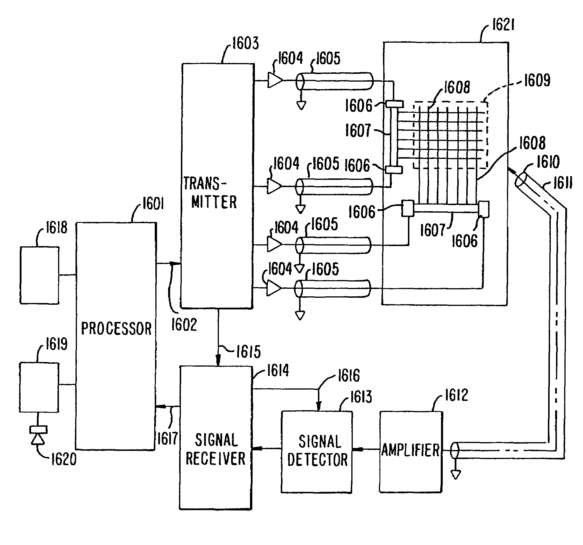
[0049]The present invention generally comprises an electrographic position sensing system, including antenna apparatus for an electrographic position location system, a method of fabricating the antenna apparatus, and the use of the antenna apparatus in an electrographic position location system. As used in this application, an electrographic location detection system is a system in which an antenna system generates a radiating electric field which may be detected a short distance proximate to the antenna surface by a stylus containing a receiving antenna element. Consequently, as used in this application, an electrographic location position system may detect the position of a stylus brought within a preselected distance from the active surface.

[0050]For detection systems similar to those shown in FIGS. 1-4 in which the equipotential lines are generated by radio frequency (rf) drive signals, for example a frequency of about 60 kHz, the equipotential lines will have an instantaneous ...


PUM


Abstract

An apparatus for use in an electrographic position sensing system comprises an antenna system and a signal strength detector. In one embodiment, the antenna system comprises two antennas. The detector measures the signal strength from each antenna. A microprocessor contains an algorithm to calculate the position of the detector near the antennas.

Description

[0001]This patent application is a continuation of U.S. patent application Ser. No. 09 / 574,499, filed on May 19, 2000 now U.S. Pat. No. 6,661,405, which claims the benefit of U.S. Provisional Patent Application No. 60 / 200,722, filed on Apr. 27, 2000, and U.S. Provisional Patent Application No. 60 / 200,960, filed on May 1, 2000, which are herein incorporated by reference in their entirety for all purposes.BACKGROUND OF THE INVENTION[0002]There are a variety of games, toys, and interactive learning devices in which a stylus is used to point to a region on a surface in order to input data or questions. There are several technologies to determine the position of a stylus on a sensing surface. One approach is to embed an array of pressure sensitive switches in the sensing surface, such as membrane switches. However, conventional membrane switches have limited resolution. Another approach consists of arrays of capacitive or inductive elements whose impedance is altered by bringing the styl...

Claims


Application Information

Patent Timeline
Patent Type & Authority Patents(United States)
IPC IPC(8): G06F3/041G06F3/033G06F3/045G06K11/06G08C21/00G01S5/02G01S19/19G01S19/36G06F3/044G06F3/046H01Q21/29
CPCG06F3/046H01Q21/29G01S5/02H01Q3/26
Inventor FLOWERS, MARK
Owner LEAPFROG ENTERPRISES
Why Eureka
Try Eureka