Laser rangefinder and method thereof

a laser rangefinder and laser technology, applied in the field of laser rangefinders, can solve the problems of not easy to detect the target signal, different from the electro-optical system, etc., and achieve the effect of accurate detection of the target signal and improved range-finding performance of the rangefinder

Inactive Publication Date: 2009-03-03
EOSYST +1
View PDF6 Cites 8 Cited by
  • Summary
  • Abstract
  • Description
  • Claims
  • Application Information

AI Technical Summary

Benefits of technology

[0008]It is an advantage of the present invention to use low-power laser diodes, and to accurately detect a target signal from a rangefinder according to a pulse detection method.
[0009]It is an advantage of the present invention to detect a target signal hidden in noise to improve range-finding performance of the rangefinder.
[0010]To achieve the advantages, a rangefinder for eyesight protection using a pulse detection method without a retroreflector according to the present invention uses characteristics that noise has non-correlation and signals have correlation to find a range to a target in the repetition rate of several thousand times per second, execute binary-quantization on the signal for each finding into a sampling frequency matched with range-finding resolving power, and accumulate data. After this, the rangefinder processes the accumulated data statistically (i.e., performs a cumulative binary detection method) to detect a target signal (a signal corresponding to a laser beam reflected from the target, and noise is canceled from the signal), and calculates a target range (a range to the target) based on the detected target signal.
[0011]In one aspect of the present invention, a method for finding a range comprises: (a) receiving laser beams reflected from a target and input, and outputting a corresponding electrical signal; (b) converting the electrical signal into range-finding data; (c) sequentially storing the range-finding data; (d) adding the stored range-finding data and previously processed and stored accumulated data, and storing results as accumulated data; (e) detecting data exceeding a threshold value from among the accumulated data as target signals; and (f) reading a target range based on the detected target signals, wherein (a) through (d) are repeated N times, and the accumulated data in (e) are obtained by repeating (a) through (d) N times.
[0012]The (a) comprises: receiving the laser beams, converting the same into a corresponding photocurrent signal, and converting the signal into a voltage signal, and (b) comprises: differentiating the voltage signal to cancel a voltage component superimposed on the voltage signal and caused by background scattering of laser beams exponentially decreasing according to ranges.
[0013]The method further comprises: filtering the differentiated signal with a predetermined frequency bandwidth identical to a frequency band of the target signal, wherein the bandwidth satisfies 0.35 / tr (tr is a rising time of a laser pulse), and a cut-off frequency satisfies ½τ (τ is a full width at half the maximum).

Problems solved by technology

However, since the high-power lasers may damage human eyes, the laser outputs have recently been regulated, and a need for rangefinders that use low-power laser diodes that are safe for the eyes has been raised.
However, since the electro-optical system shoots modulated laser beams toward a retroreflector installed on a target location, and detects a phase of the signal reflected from the retroreflector to find a range, it is far different from the electro-optical system that uses a pulse detection method without the retroreflector in the principle of signal processing techniques.
Since an output of the target signal reflected from the target is less than the system noise including optical noise, detector noise, and amplifier noise in the electro-optical system using low-power laser diodes and the pulse detection method, it is not easy to detect the target signal.

Method used


Image

  • Laser rangefinder and method thereof
  • Laser rangefinder and method thereof
  • Laser rangefinder and method thereof

Examples


Embodiment Construction

[0030]In the following detailed description, only the preferred embodiment of the invention has been shown and described, simply by way of illustration of the best mode contemplated by the inventor(s) of carrying out the invention. As will be realized, the invention is capable of modification in various obvious respects, all without departing from the invention. Accordingly, the drawings and description are to be regarded as illustrative in nature, and not restrictive.

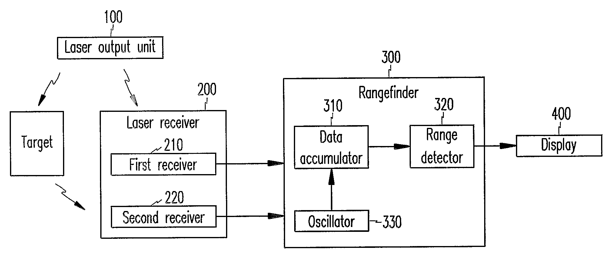
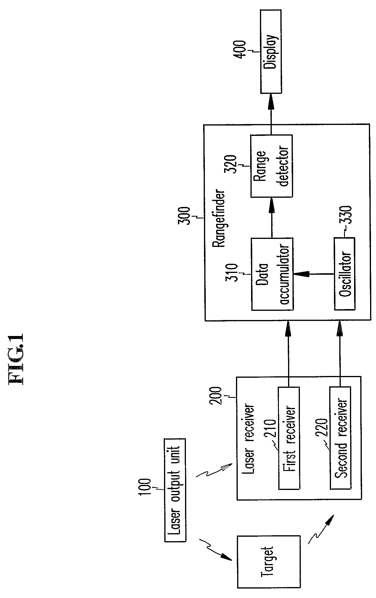
[0031]FIG. 1 shows a block diagram of a laser rangefinder according to a preferred embodiment of the present invention.

[0032]As shown, the laser rangefinder comprises a laser output unit 100 for outputting laser beams to a target, a laser receiver 200 receiving the laser beams reflected from the target and outputting corresponding electrical signals, a rangefinder 300 for finding a range up to the target based on the received signals, and a display 400 for displaying the found range.

[0033]The laser output unit 100 comp...


PUM


Abstract

Disclosed is a laser rangefinder and method thereof. By using characteristics that noise has non-correlation and signals have correlation, laser beams are output to a target to find a range to the target with iteration rates of thousands of times per second, signals for each range-finding are binary-quantized using a sampling frequency corresponding to a range-finding resolving power, and data are accumulated. After this, the accumulated data are processed in a statistical manner to detect a target signal and produce a target range based on the target signal. According to the present invention, the rangefinder for outputting low-power laser beams, using the laser beams reflected from the target, and detecting a range to the target, easily and accurately detects target signals in the noise.

Description

BACKGROUND OF THE INVENTION[0001](a) Field of the Invention[0002]The present invention relates to a rangefinder. More specifically, the present invention relates to a laser rangefinder and method thereof.[0003](b) Description of the Related Art[0004]Conventional laser rangefinders generally use high-power lasers of several megawatts, and intensities of signals reflected from a target (target signals) are much higher than those of system noise including optical noise, detector noise, and amplifier noise, and accordingly, the laser rangefinders easily detect the target signals through a simple threshold detection method.[0005]However, since the high-power lasers may damage human eyes, the laser outputs have recently been regulated, and a need for rangefinders that use low-power laser diodes that are safe for the eyes has been raised. Thus, new signal processing technology studies for increasing the ranges have actively progressed.[0006]A representative laser diode rangefinder for eyes...

Claims


Application Information

Patent Timeline
Patent Type & Authority Patents(United States)
IPC IPC(8): G01B5/02G01B11/02G01B7/14G01B11/14G01B5/14G01B7/02G01B13/02G01C3/00G01S17/10G01S7/487
CPCG01S17/10G01S7/4873G01C3/00
Inventor LEE, SEOK-HWANLEE, JAE-YOUNGNAM, KI-CHOULKANG, KYUNG-MOKYOO, GEUN-SIK
Owner EOSYST
Why Eureka
Try Eureka