

Emulsion atomizer nozzle, and burner, and method for oxy-fuel burner applications
a technology of atomizer and oxy-fuel burner, which is applied in the direction of explosives, combustion types, combustion using lump and pulverulent fuel, etc., can solve the problems of liquid breakage, non-uniform heat delivery and local overheating, and the limited use of oxy-fuel burners
Inactive Publication Date: 2009-03-10
AIR PROD & CHEM INC
View PDF14 Cites 32 Cited by
- Summary
- Abstract
- Description
- Claims
- Application Information
AI Technical Summary
Benefits of technology
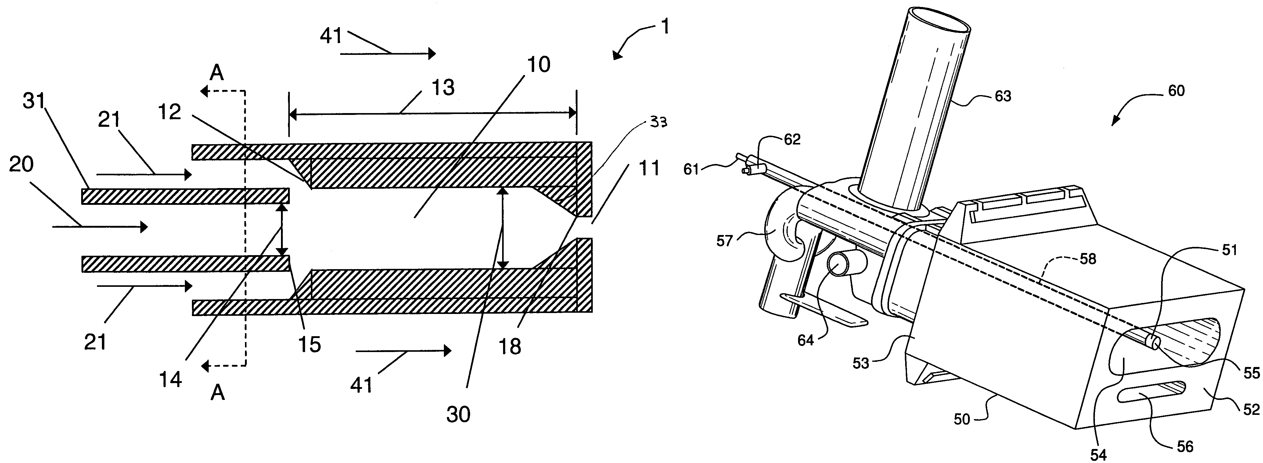
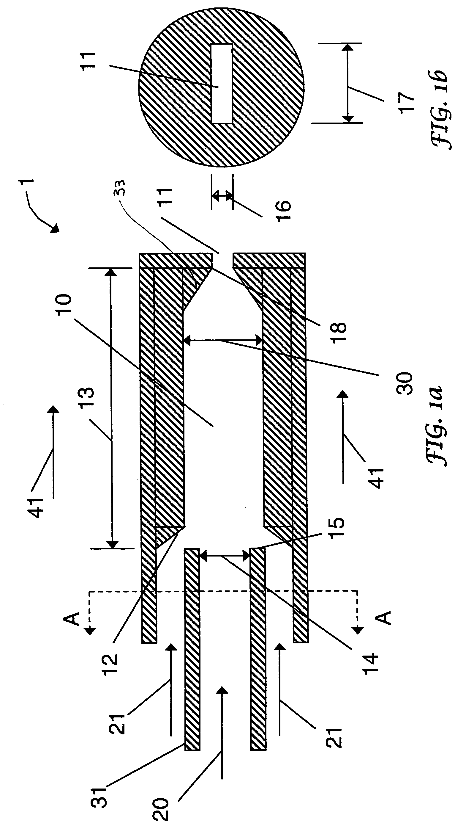
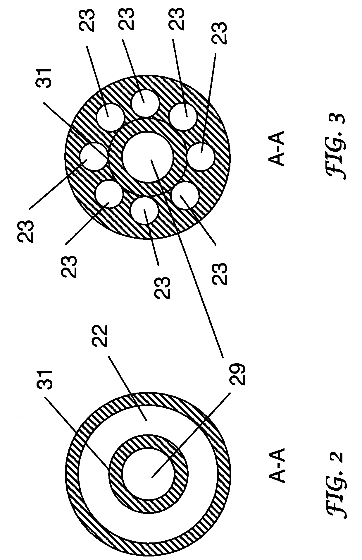
This patent describes a method for oxy-fuel combustion, which involves mixing liquid fuel and atomizing gas in an emulsion chamber to create a fast-moving mixture. This mixture is then discharged through a rectangular-shaped orifice into an oxygen-enriched oxidizer stream. The technical effects of this invention include improved combustion efficiency, reduced emissions, and improved control over the combustion process. Additionally, the invention provides a nozzle and burner for oxy-fuel combustion that facilitate the mixing of liquid fuel and atomizing gas in the emulsion chamber.
Problems solved by technology
The flames are short, tight, leading to non-uniform heat delivery and local overheating.2) Internal-mixing or emulsion, where the atomizing gas and liquid fuel are mixed inside an internal chamber, and the two-phase mixture is then ejected through an exit orifice causing liquid breakup due to depressurization of inter-mixed gaseous phase.
While the internal-mixing atomizers are widely used in air-fuel combustion, their use in oxy-fuel burners have been limited due to cooling concerns and possible flame flash-back issues.
However, for oxy-fuel burners, which are burners utilizing a primary oxidizer with a higher O2 concentration than air, cooling of the atomizing nozzle via the reduced volume of the primary oxidizer may be unsatisfactory.
In addition, oxy-fuel burners have much higher flame temperatures.
Higher internal-mixing nozzle temperatures lead to several potential problems:1) Elevated nozzle temperatures may cause chemical degradation of liquid fuels prior to their introduction into the furnace.
More specifically, for fuel oils, such as heavy oils with high sulfur content, and oils with high carbon residue values (CCR) (e.g. oils with high levels of asphaltenes), high nozzle temperatures may lead to internal coke deposition and nozzle plugging.
Method used
View moreImage
Smart ImageViewing Examples

Examples
example 2
Atomizer Nozzle with Emulsion Velocity Less than 12 m / s
[0043]An atomizer nozzle according to the invention was tested having an emulsion velocity varying from 8 to 12 m / s, and residence time between 500 to 800 μs for No. 6 fuel oil having flow rates from 50 to 200 liters per hour. The nozzle was positioned close to the hot face as illustrated in FIG. 4. The necessity to clean the nozzle was reduced to less than once a month.
Login to View More PUM
| Property | Measurement | Unit |
|---|---|---|
| velocity | aaaaa | aaaaa |
| mean residence time | aaaaa | aaaaa |
| diameter | aaaaa | aaaaa |
Abstract
A method for oxy-fuel combustion, the method comprising the steps of: introducing a liquid fuel into an emulsion chamber through a liquid fuel conduit having an effective diameter, the emulsion chamber having a length that is 2 times or less than 2 times of said effective diameter of said liquid fuel conduit; introducing an atomizing gas into the emulsion chamber through at least one atomizing gas conduit; mixing the liquid fuel and the atomizing gas in said emulsion chamber to create an emulsion mixture that has a mean residence time in said emulsion chamber of from 500 to 800 μs, the emulsion mixture having an emulsion mixture velocity less than or equal to 12 m / s; and discharging said emulsion mixture through a generally rectangular-shaped orifice into an oxygen-enriched oxidizer stream. A nozzle and burner for oxy-fuel combustion are also disclosed.
Description
[0001]This patent application claims the benefit of a provisional patent application U.S. Ser. No. 60 / 536,964, filed Jan. 16, 2004 that is incorporated herein by reference.FIELD OF THE INVENTION[0002]The present invention pertains to liquid fuel nozzles for oxygen based combustion and methods of using them for producing elevated temperatures in industrial melting furnaces.BACKGROUND OF THE INVENTION[0003]Use of atomizer nozzles is known in the art as illustrated in U.S. Pat. Nos. 5,547,368, 5,567,141, 5,393,220 and 5,617,997, incorporated herein by reference in their entirities. As described in U.S. Pat. No. 5,547,368, atomizer nozzles are used in industrial melting furnaces for such diverse products as metals, glass, ceramic materials, and the like.[0004]There are many ways of atomizing liquid fuels in combustion applications. The nozzles can be grouped in two major groups:[0005]a) Pressure atomizers, where relatively high liquid fuel pressure is used to drive the flow through a sm...
Claims
Login to View More Application Information
Patent Timeline
 Patent Type & AuthorityPatents(United States)
IPC IPC(8): F23C5/00C06B45/00F23D11/10F23D11/14F23L7/00
CPCF23D11/102F23D11/14F23D11/38F23D11/40F23L7/007F23D2900/00006Y02E20/322Y02E20/344Y02E20/34F23D11/16
InventorDUDILL, ROGERMILLINGTON, DAVID
OwnerAIR PROD & CHEM INC