Electric wind instrument and key detection structure thereof

a technology for wind instruments and key detection, applied in instruments, pulse techniques, keyboard-like device coding, etc., can solve the problems of cumbersome and difficult operation of disassembly of keys and the like at the time of repair or care of wind instruments, cumbersome and cumbersome, etc., and achieves the effect of simple construction and easy attachment and removal

Inactive Publication Date: 2009-03-10
YAMAHA CORP
View PDF37 Cites 10 Cited by
  • Summary
  • Abstract
  • Description
  • Claims
  • Application Information

AI Technical Summary

Benefits of technology

[0008]In view of the foregoing, it is an object of the present invention to provide a key detection structure for a wind instrument which is simple in construction and allows each detector unit to be attached and detached with ease.
[0011]According to the present invention, the individual detector units can be attached and detached with ease and promptly by just inserting and taking the retaining member into and out of the tubular body. With the detector units kept in non-contacting relation to the corresponding keys, the present invention can eliminate the needs for attaching the detector units with respect to the individual keys and placing the detector units in the tone holes, with the result that not only the key detection structure can be simplified in construction but also constraints or limitations in design, such as a size, of the detector units can be significantly lessened. In addition, the present invention can save labor in diassembling the keys from the tubular body and also reduce workload necessary for care and repair of the wind instrument.
[0012]Preferably, the retaining member includes an axially-extending member extending along the axis of the tubular body, and a plurality of contact portions provided on the axially-extending member and pressed against the inner peripheral surface of the tubular body. With the contact portions pressed against the inner peripheral surface of the tubular body, the retaining member can be supported by the inner peripheral surface of the tubular body in such a manner that it is freely attachable and detachable to and from the tubular body, even where the inner surface of the tubular body is a smooth surface as in a so-called acoustic-type wind instrument. Further, the retaining member can be moved, by application of an external force, to allow the contact portions to be displaced little by little within the tubular body, so that fine adjustment of the installed position of the detector units can be made with ease. Furthermore, with the detector units provided on the single axially-extending member at positions corresponding to the keys, the present invention can even further expedite the installation operation.
[0013]Preferably, the axially-extending member has at least two retaining surfaces oriented in different directions, and these retaining surfaces are constructed to retain thereon the detector units. Thus, even where the wind instrument has keys oriented in two different directions, e.g. in an upward direction and obliquely-downward direction as viewed from a human player of the instrument, the detector units corresponding to the differently oriented keys can be readily fixed in predetermined positions via the single axially-extending member.
[0014]Preferably, each of the detector units comprises a photo reflector. Thus, in the present invention, a distance between the photo reflector and the key can be detected accurately, so that the opening / closing state of the key can be detected with a high accuracy.
[0015]Preferably, a reflector member or refractor member is provided between each of the detector units and the key corresponding to the detector unit so that light emitted by the photo reflector can be reflected or refracted by the reflector member or refractor member. Thus, where the light emitted by the photo reflector is reflected or refracted via the reflector or refractor member, the light emitted by the photo reflector can be appropriately directed to fall on the back surface of the key irrespective of the orientation of the photo reflector, with the result that the present invention can reduce the positional constraints of the detector units and thereby enhance the design freedom.

Problems solved by technology

However, structure (1) above would present the inconvenience that operation for attaching the magnetic member to the position adjacent to the back surface of the key requires is very cumbersome and requires a great amount of time.
The inconvenience is due to the fact that, during the attaching operation, it is essential to attach the magnetic member after detaching or disassembling the key from the tubular body and insert the magnetic member into a narrow space between the tubular body and the key.
Further, structure (2) above would present the inconveniences that operation for attaching the hall element to the outer peripheral surface of the tubular body and a construction for supporting the magnetic member via the arm tend to be very complicated, and that operation for disassembling the key and the like at the time of repair or care of the wind instrument tends to be cumbersome and difficult.
In particular, because the outer peripheral surface of the tubular body is a curved surface, the attached state of the hall element tends to be unstable.

Method used


Image

  • Electric wind instrument and key detection structure thereof
  • Electric wind instrument and key detection structure thereof
  • Electric wind instrument and key detection structure thereof

Examples


Embodiment Construction

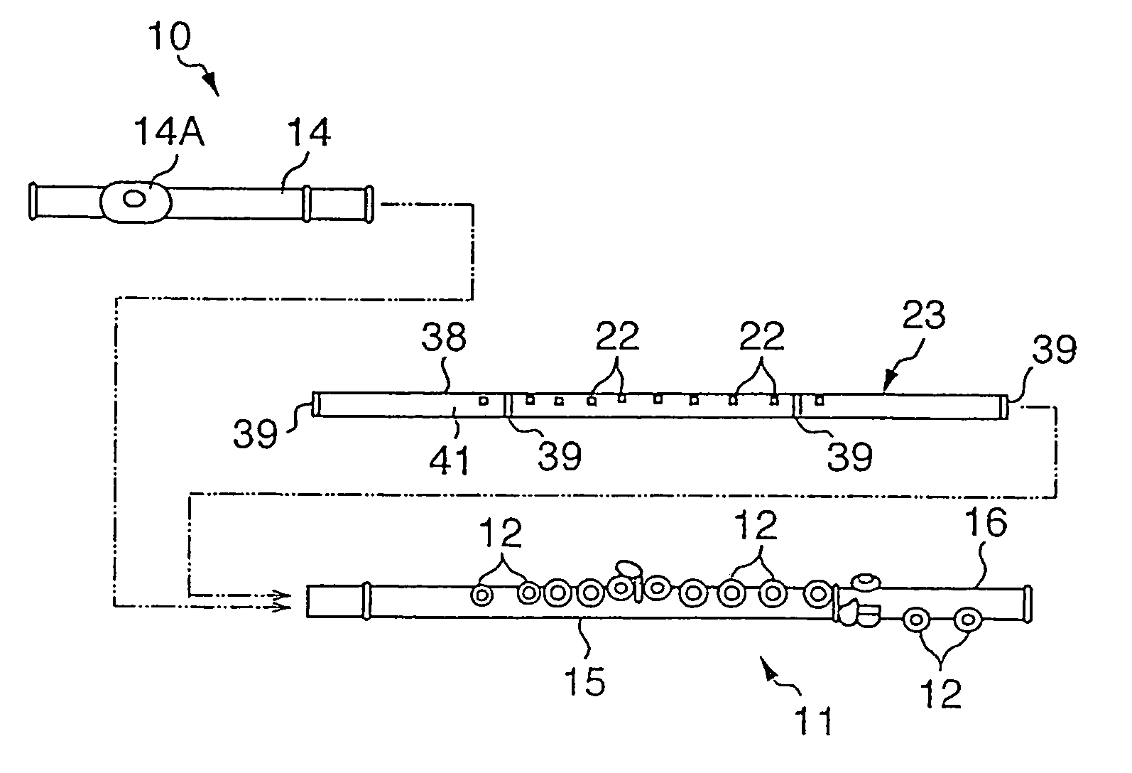
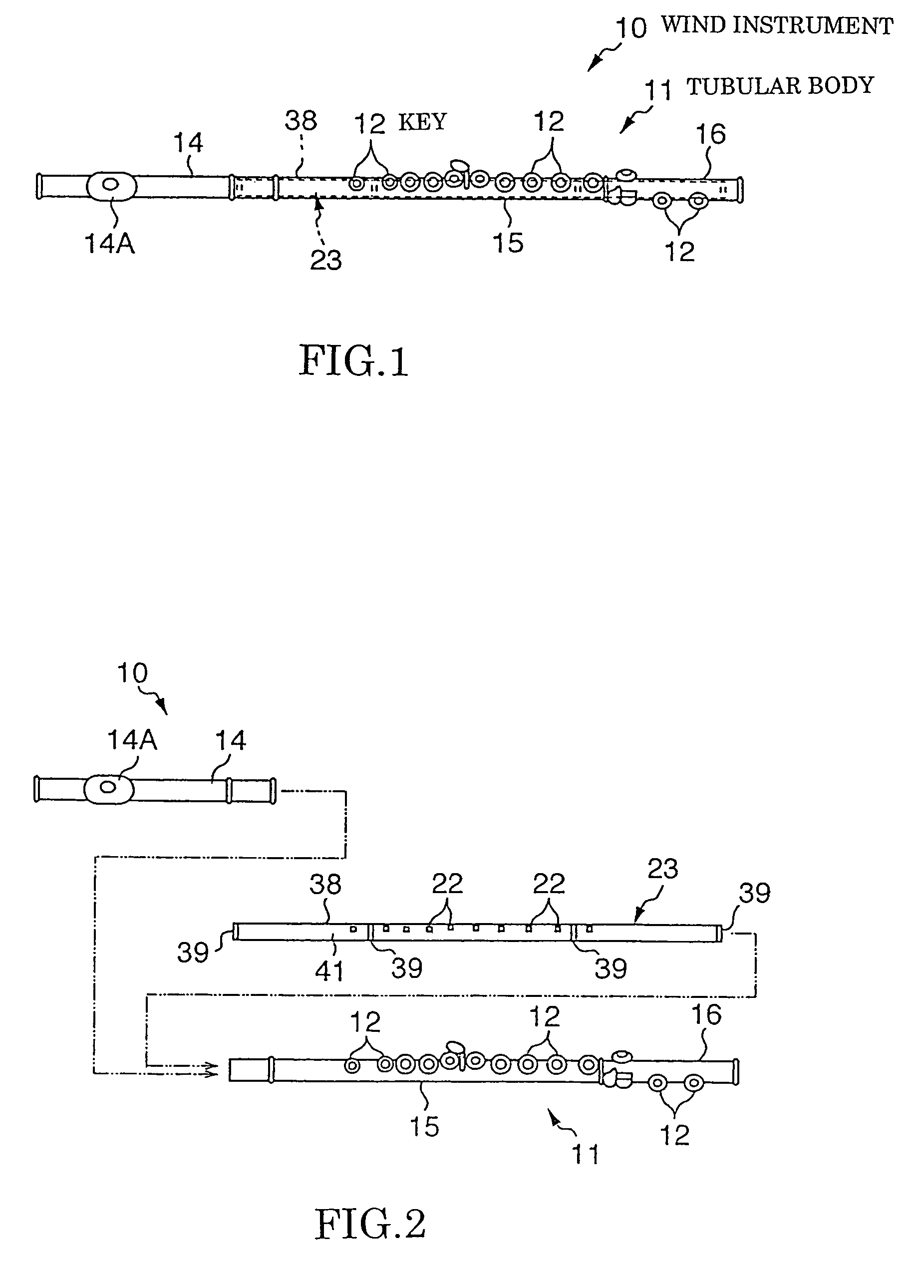
[0029]FIG. 1 is a schematic plan view of a wind instrument to which is applied a key detection structure in accordance with an embodiment of the present invention, and FIG. 2 is an exploded view of the wind instrument shown in FIG. 1. This wind instrument 10 is in the form of an acoustic-type flute of the conventionally-known construction, which can perform predetermined tone pitches by vibrating air using any of the conventional performance styles. The wind instrument 10 comprises a tubular body 11 extending in a left-right direction of FIG. 1, and a plurality of keys 12 provided on the tubular body 11.

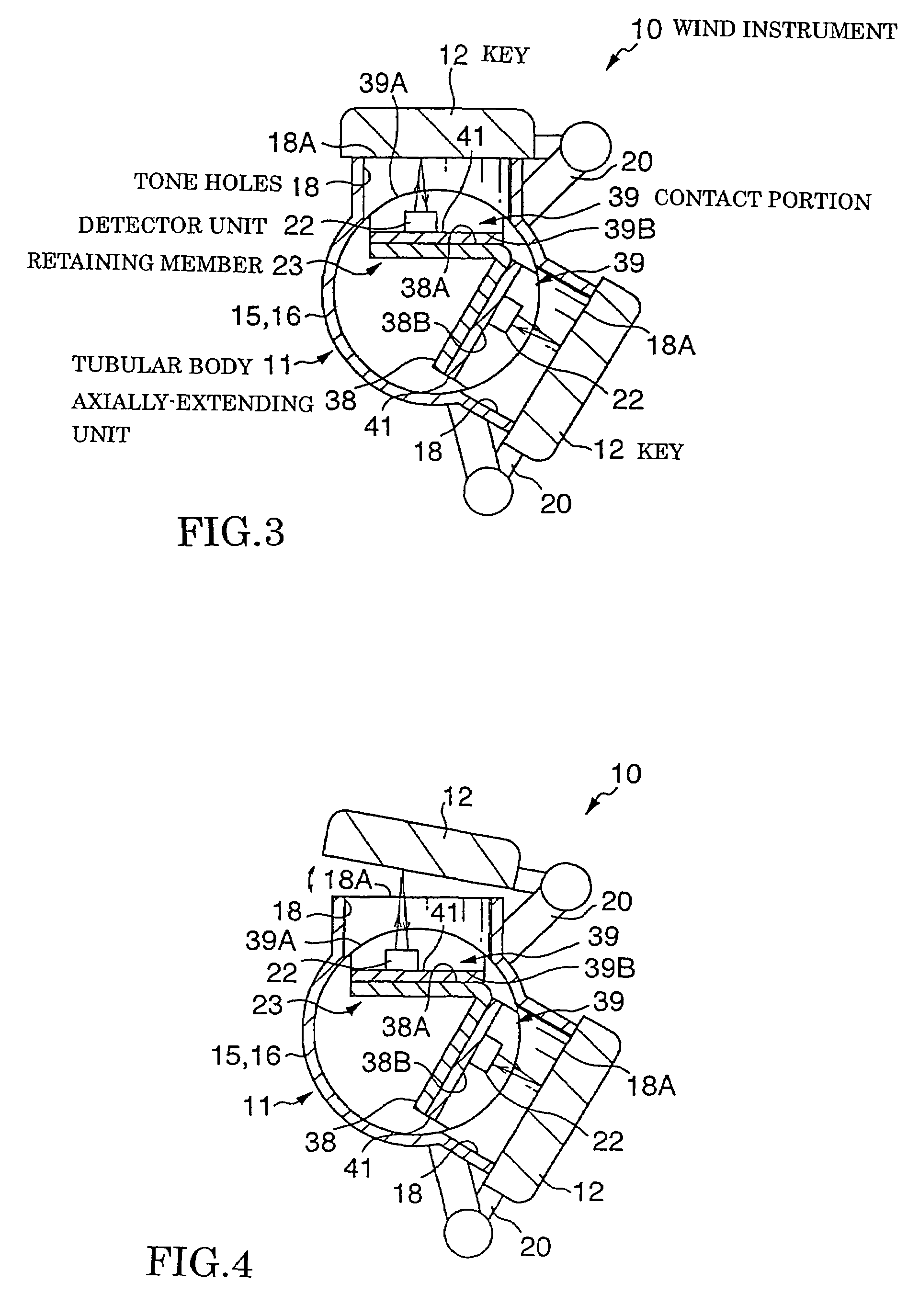
[0030]The tubular body 11 comprises a head joint (or head section) 14 having an embouchure plate 14A, a main tube (or main body) 15 connectable to one end (right end in FIG. 2) of the head joint 14, and a foot joint (or tail section) 16. As seen from a schematic vertical sectional view of FIG. 3, the main tube 15 and foot joint 16 have a plurality of tone holes 18 formed therethrough...


PUM


Abstract

Wind instrument includes a tubular body having a plurality of tone holes, and a plurality of keys capable of opening and closing the tone holes. Via a retaining member, detector units are provided within the tubular body in corresponding relation to the keys, and each of the detector units is generally opposed to the back surface of the corresponding key. Each of the detector units detects a relative distance to the back surface and outputs an electrical signal, on the basis of which an opening / closing state of the key can be detected. The retaining member, accommodated in the tubular body, positions and retains each of the detector units in such a manner that the keys and tubular body and the individual detector units are kept in non-contacting relation to each other.

Description

BACKGROUND OF THE INVENTION [0001]The present invention relates generally to key detection structures for wind instruments, and more particularly to an improved key detection structure for a wind instrument which allows detector units, for detecting states etc. of corresponding keys, to be readily attached and detached to and from the wind instrument.[0002]There have been known key detection structures of a type which reproduces electronic tones by detecting operation of keys on a wind instrument, and examples of such a type of key detection structure are disclosed in Japanese Utility Model Application Laid-open Publication No. HEI-4-89999 and Japanese Patent Application Laid-open Publication No. HEI-8-305362. According to the disclosure of the No. HEI-4-89999 and No. HEI-8-305362 publications, a module including switches and hall elements is previously incorporated in a tubular body and keys forming the wind instrument. Namely, the wind musical instruments disclosed in these public...

Claims


Application Information

Patent Timeline
Patent Type & Authority Patents(United States)
IPC IPC(8): G10H1/34H03K17/94H03K17/969
CPCG10D9/043G10G3/04G10H1/34G10H2220/305G10H2230/195Y10S84/07G10D9/047
Inventor SHIBATA, KOICHIRO
Owner YAMAHA CORP
Why Eureka
Try Eureka