Magnetic resonance imaging apparatus and method of conveying the magnetic resonance imaging apparatus

a magnetic resonance imaging and magnetic resonance imaging technology, applied in the direction of instruments, using reradiation, radiating element structural forms, etc., can solve the problems of increasing costs and achieve the effect of reducing the cable laying tim

Inactive Publication Date: 2009-03-10
GE MEDICAL SYST GLOBAL TECH CO LLC
View PDF14 Cites 8 Cited by
  • Summary
  • Abstract
  • Description
  • Claims
  • Application Information

AI Technical Summary

Benefits of technology

[0019]According to the invention it is possible to provide a magnetic resonance imaging apparatus and a magnetic resonance imaging apparatus conveying method both permitting reduction of the cable laying time.

Problems solved by technology

These works are an obstacle to shortening of the time required for installation of the magnetic resonance imaging apparatus, causing an increase of cost.

Method used


Image

  • Magnetic resonance imaging apparatus and method of conveying the magnetic resonance imaging apparatus
  • Magnetic resonance imaging apparatus and method of conveying the magnetic resonance imaging apparatus
  • Magnetic resonance imaging apparatus and method of conveying the magnetic resonance imaging apparatus

Examples


Embodiment Construction

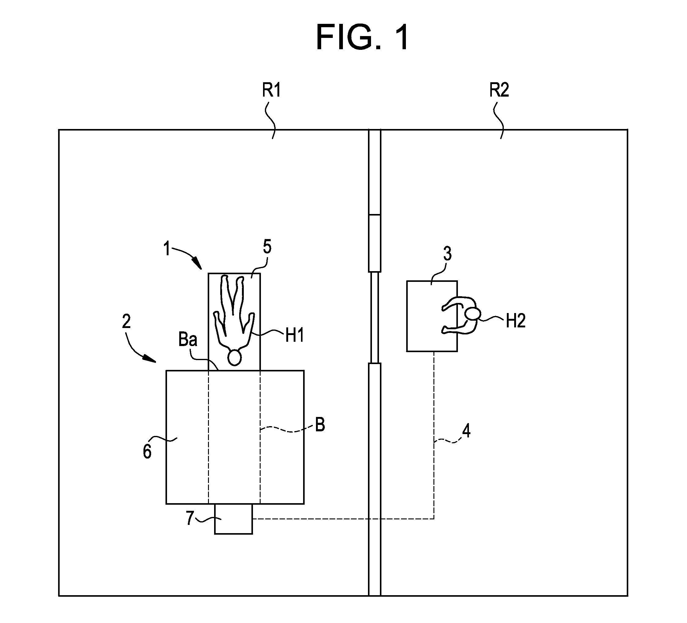
[0025]FIG. 1 is a plan view showing schematically the construction and layout of a magnetic resonance imaging apparatus (MRI apparatus) according to an embodiment of the invention.

[0026]The MRI apparatus, indicated at 1, includes a body 2 disposed in a scan room R1 to pick up an image of a subject H1, an operation console 3 disposed in an operation room R2 and accepting operation of an operator H2 for the MRI apparatus, and plural cables 4 (e.g., ten or more, only one is shown in FIG. 1) for connecting the body 2 and the operation console 3 with each other.

[0027]The scan room R1 is constructed so as to prevent the entry of radiation electromagnetic wave leaking from the body 2 and disturbance electromagnetic wave. The plural cables 4 extend from the scan room R1 to the operation room R2 through a pit or duct.

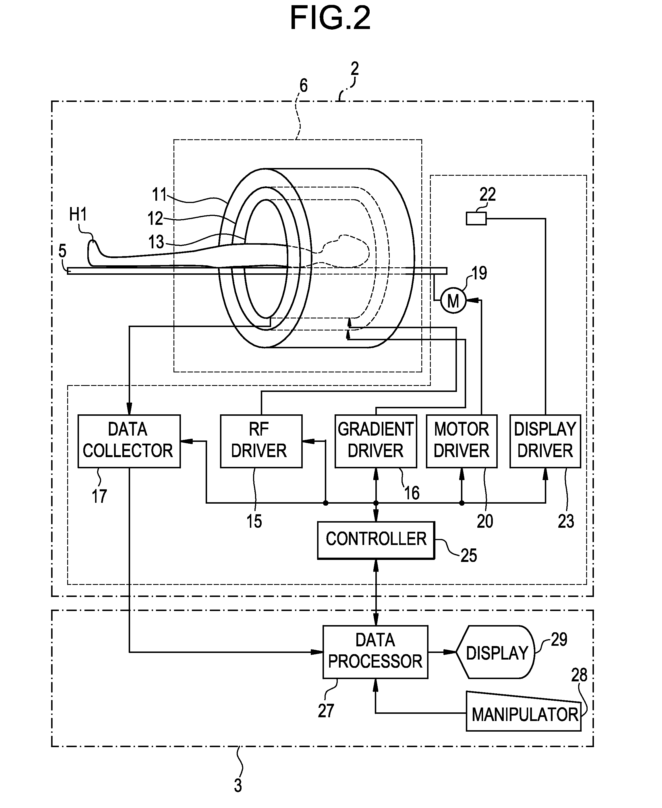
[0028]The body 2 includes a cradle 5 for conveyance of the subject H1, a magnet section 6 for application of a magnetic field to the subject H1 and for reception of a magnetic r...


PUM


Abstract

With a view to shortening the cable laying time there is provided a magnetic resonance imaging apparatus for generating an image of a subject in accordance with a magnetic resonance signal received after application of a high-frequency magnetic field to the subject under a static magnetic field and a gradient magnetic field, the magnetic resonance imaging apparatus comprising a base, operating portions provided in the base and performing predetermined operations, such as a data collector and a controller, two pipes projecting from the base, and plural cables wound in the figure of 8 onto projecting portions of the two pipes projecting from the base, one end of the cables being connected electrically to the operating portions.

Description

CROSS REFERENCE TO RELATED APPLICATIONS[0001]This application claims the benefit of Japanese Application No. 2006-167392 filed Jun. 16, 2006.BACKGROUND OF THE INVENTION[0002]The present invention relates to a magnetic resonance imaging apparatus and a method of conveying the magnetic resonance imaging apparatus.[0003]In a magnetic resonance imaging apparatus, a magnet section for applying a magnetic field to a subject and receiving a magnetic resonance signal from the subject is disposed in a magnet room and an operation console for controlling the operation of the magnet section is disposed in an operation room (see, for example, Patent Literature 1). The magnet section and the operation console are connected together through plural (for example, ten or more) cables.[0004]At the time of shipping of the magnetic resonance imaging apparatus, the plural cables are conveyed separately from the magnet section in a state in which the cables are wound like coils in the same direction, and...

Claims


Application Information

Patent Timeline
Patent Type & Authority Patents(United States)
IPC IPC(8): G01V3/00H01Q1/36H01Q1/42
CPCG01R33/28
Inventor KAWACHI, HISASHIOHGISHI, NORIFUMIITO, NOBUTAKA
Owner GE MEDICAL SYST GLOBAL TECH CO LLC
Why Eureka
Try Eureka