
Method and apparatus for implementing soft switching in a class D amplifier

a class d amplifier and soft switching technology, applied in amplifiers, amplifiers with semiconductor devices/discharge tubes, electrical devices, etc., can solve the problems of reducing efficiency, limiting the switching frequency bandwidth, power which must be dissipated, etc., to reduce efficiency, reduce power loss, and high power loss

Active Publication Date: 2009-03-10
RGB SYST INC
View PDF7 Cites 12 Cited by
  • Summary
  • Abstract
  • Description
  • Claims
  • Application Information

AI Technical Summary

Benefits of technology

"The invention is a way to reduce the power loss in class D amplifiers, which are commonly used in audio equipment. The problem is that high frequency switching in these amplifiers causes negative effects like degraded audio quality. To address this, the invention takes advantage of the ripple in the switching process to significantly reduce power loss. This allows for improved efficiency and increased switching frequency. Additionally, the invention uses coupled inductor methods to steer the ripple away from the output of the amplifier, eliminating any negative effects on audio performance."

Problems solved by technology

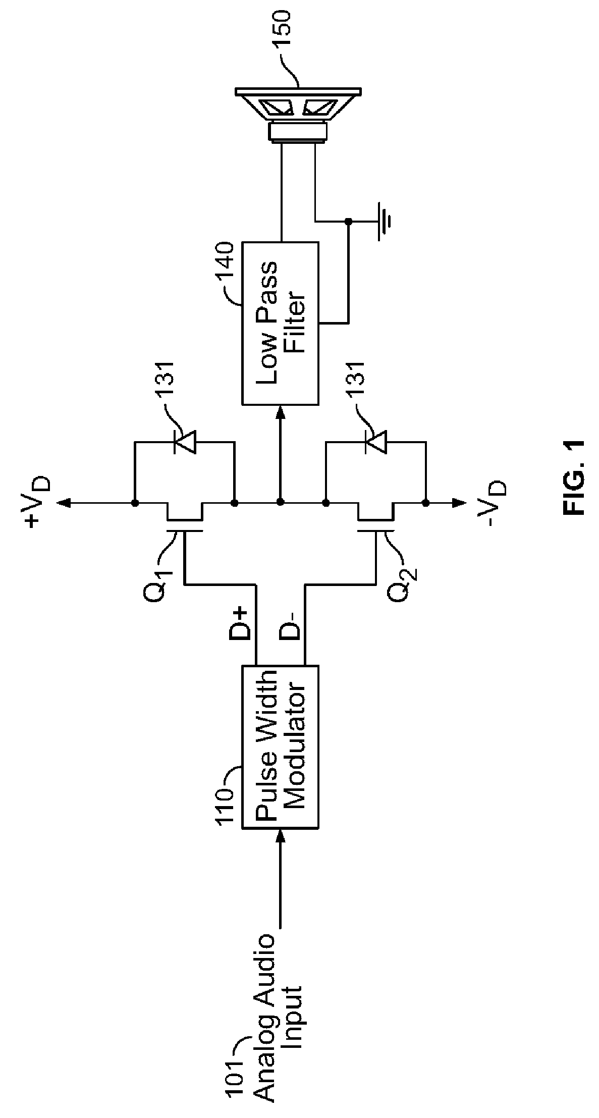
Because of the negative effects of high frequency ripple, including degradation in the audio reproduction, prior art Class D designs trade power loss (i.e. accept higher power loss) for reduced ripple by sizing the output inductor large enough to limit ripple to no more than 20% of the load current.
The high power loss (therefore reduced efficiency) is due to the transistors switching when the voltage and current are simultaneously at peak positive values resulting in power which must be dissipated.
The high positive current is a product of the relatively large inductor value, which also limits the switching frequency bandwidth.

Method used


Image

  • Method and apparatus for implementing soft switching in a class D amplifier
  • Method and apparatus for implementing soft switching in a class D amplifier
  • Method and apparatus for implementing soft switching in a class D amplifier

Examples


Embodiment Construction

[0045]The invention comprises a method and apparatus for reducing switching losses in Class D amplifiers. In the following description, numerous specific details are set forth in order to provide a more thorough description of the present invention. It will be apparent, however, to one skilled in the art, that the present invention may be practiced without these specific details. In other instances, well-known features have not been described in detail so as not to obscure the invention.

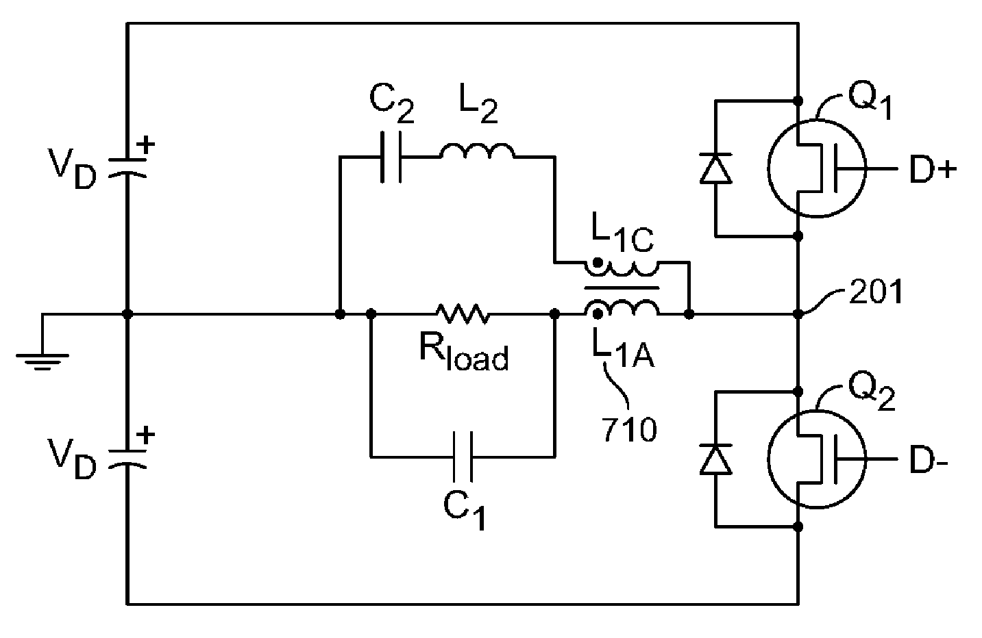
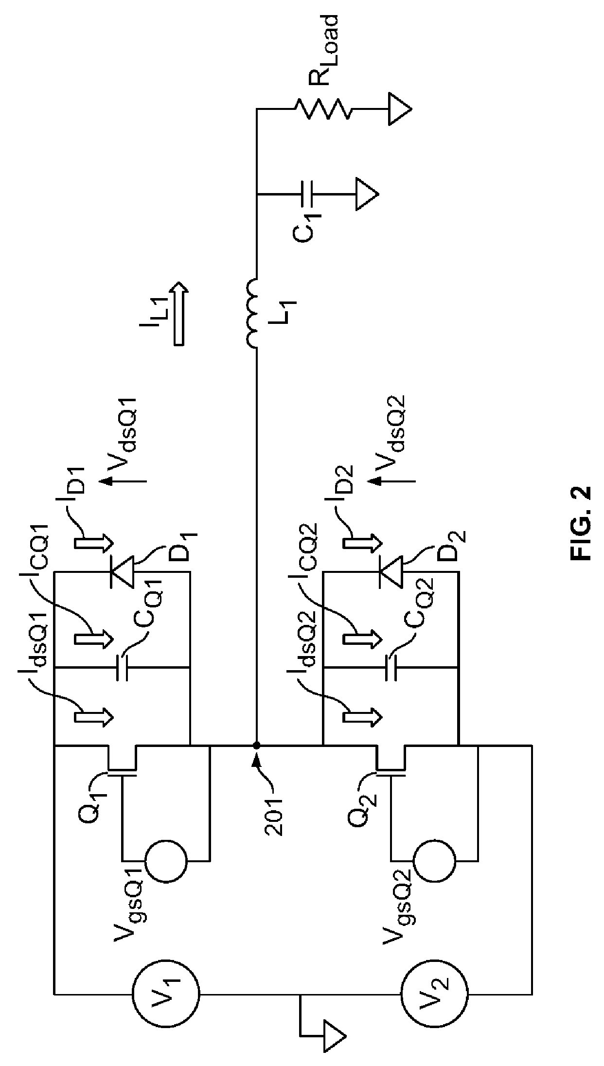
[0046]In general, embodiments of the present invention provide lossless switching class D amplifiers without the negative effects of ripple. Switching losses of prior art class D amplifiers (described with respect to Q1 turning on against diode D2) are only substantial due to the inductor current being positive at the time of transition (see waveform IL1 1403 in FIG. 14). Thus, if the inductor current were negative during this switching transition, Q2 turn off would let the inductor current charge CQ...


PUM


Abstract

The present invention provides lossless switching by configuring the output inductor so that the ripple current amplitude at load conditions results in small negative current during switching. The reconfigured output inductor results in increased ripple current amplitude. This increased ripple amplitude may be further controlled using zero ripple steering techniques to eliminate ripple at the output capacitor. A ripple steering technique involves adding a secondary output to the class D amplifier which steers the switching ripple away from the main output thus substantially relieving the main output from a major artifact of prior art Class D amplifiers.

Description

CROSS REFERENCE TO RELATED APPLICATIONS[0001]This application claims priority of U.S. Provisional Application No. 60 / 704,241 filed on Jul. 28, 2005, entitled “Method and Apparatus for Implementing Soft Switching in a Class D Amplifier”; and is a Continuation-In-Part of U.S. application Ser. No. 10 / 908,063, filed on Apr. 26, 2005, entitled “Method and Apparatus for Reducing Ripple in Class D Amplifiers”, now U.S. Pat. No. 7,167,048, which claims priority of U.S. Provisional Application No. 60 / 565,261 filed on Apr. 26, 2004, entitled “Class D Amplifier with Reduced Ripple and Increased Bandwidth,” specifications of which are herein incorporated by reference.FIELD OF THE INVENTION[0002]The present invention relates to Class D amplifiers. More specifically, it relates to reduction of switching losses in Class D amplifier circuits.BACKGROUND OF THE INVENTION[0003]High quality audio power amplifiers are traditionally large, heavy, and inefficient. Typically these equipments are capable of...

Claims


Application Information

Patent Timeline
Patent Type & Authority Patents(United States)
IPC IPC(8): H03F3/217
CPCH03F3/217H03F3/2173H03F2200/459
Inventor MENDENHALL, ERIC
Owner RGB SYST INC
Learn More