Radiation therapy machine with triple KV/MV imaging

Inactive Publication Date: 2009-03-10
CABLON MEDICAL +1
View PDF16 Cites 30 Cited by
  • Summary
  • Abstract
  • Description
  • Claims
  • Application Information

AI Technical Summary

Benefits of technology

[0009]Accordingly, it is an object of this invention to provide real time or near real time imaging for

Problems solved by technology

However, the collimation of the field is meant to be an exact measure, but because positioning a patient exactly the same on the therapy machine as on the simulator is inexact at best, it must be verified at the therapy machine prior to treatment.
This can result in the prescribed dose being applied incorrectly to the treatment volume, which can subject the patient's surrounding tissues to unnecessary radiation.
Prior attempts to use the high energy radiation from the treatment machine to produce images have resulted in low resolution and poor contrast response.
In many cases a flat panel imager has been employed for this purpose, but the imager produces only very faint images of the affected tissues, and the imager itself is eventually deg

Method used


Image

  • Radiation therapy machine with triple KV/MV imaging
  • Radiation therapy machine with triple KV/MV imaging
  • Radiation therapy machine with triple KV/MV imaging

Examples


Embodiment Construction

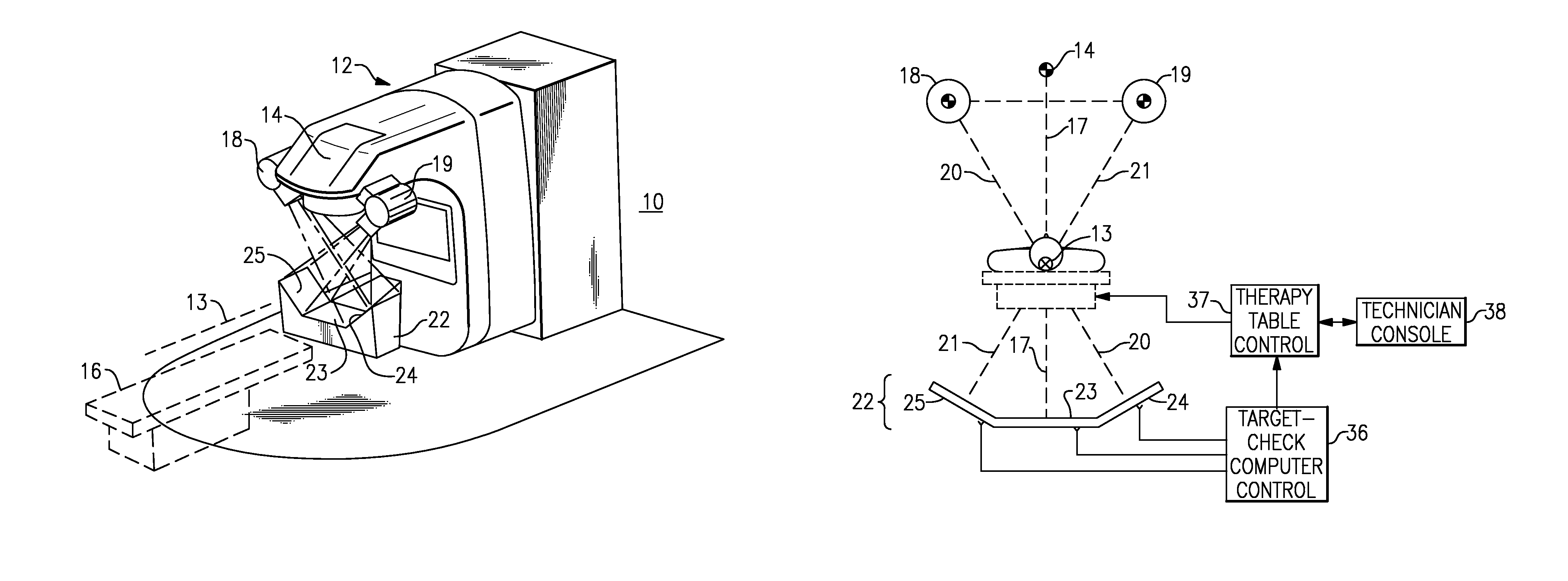
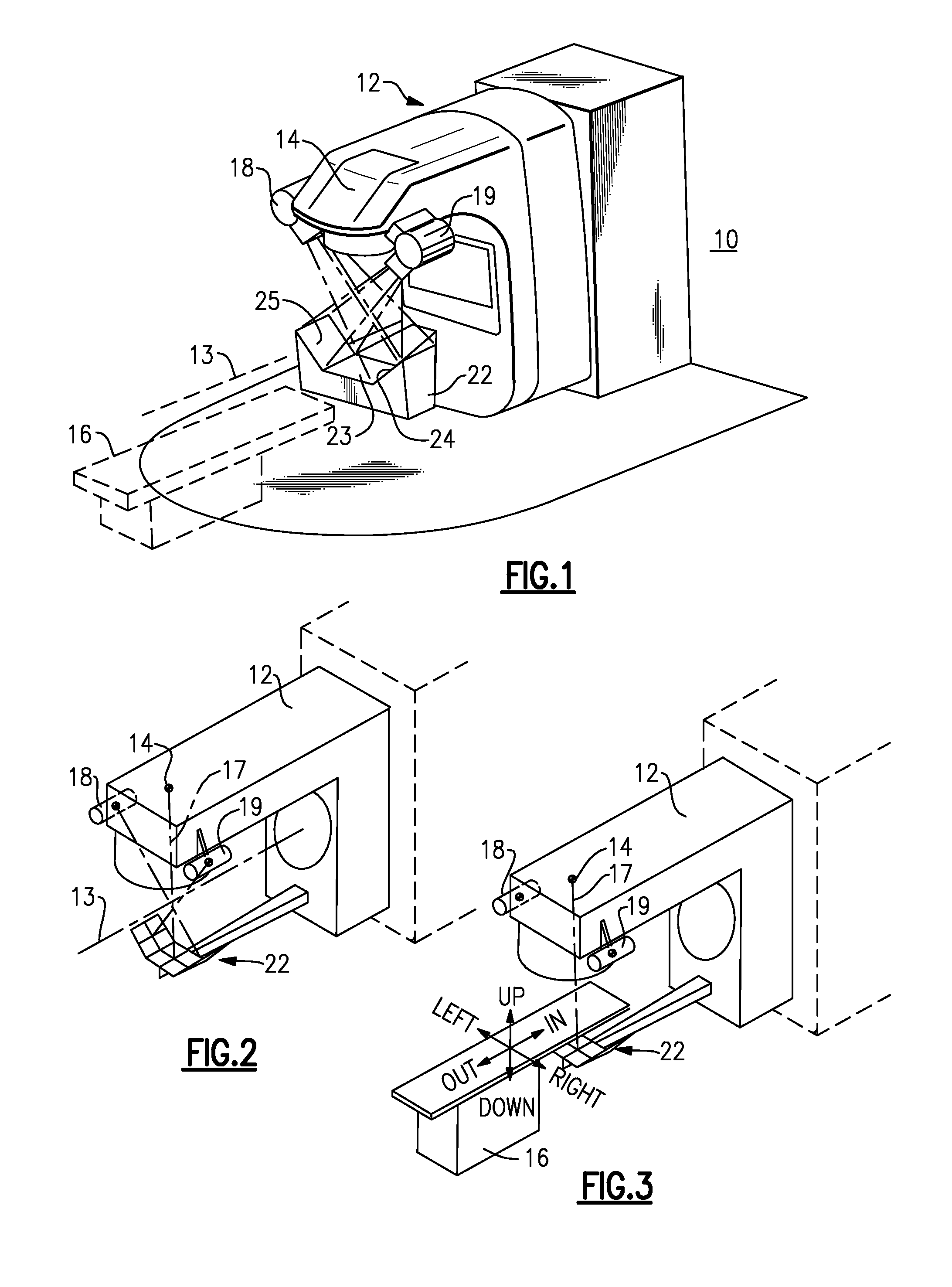
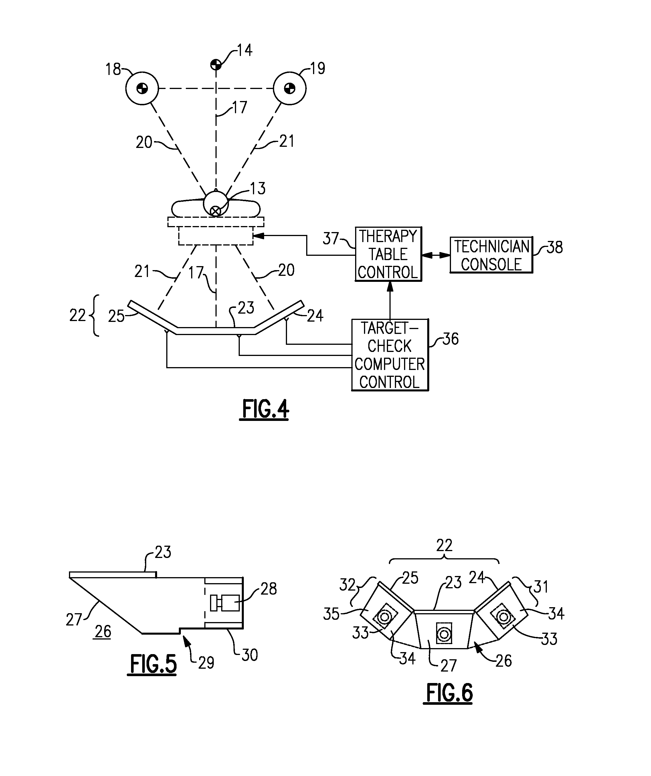
[0027]With reference to the Drawing, and initially to FIG. 1, a radiology treatment or therapy machine 10 is shown to have a gantry 12 which rotates about an axis 13 of the mechanical isocenter. A high energy radiotherapy treatment head 14, e.g., with an energy of up to 25 Mev, is mounted on the gantry 12 and positioned to emit the radiotherapy beam radially across the axis 13 of the isocenter. A treatment table or couch 16 is provided to place the patient in a proper position for administration of the dose to the patient's affected tissues, so that the table presents the patient relative to the radiotherapy isocenter. The megavolt (Mev) radiotherapy head 14 emits its energy along a beam axis 17 that passes through the patient on the table 16.

[0028]A pair of lower energy kilovolt (kV) radiation sources 18 and 19, that is, diagnostic x-ray sources, are mounted on left and right sides of the radiotherapy head 14, and each of these directs its radiation vertically along its respective ...


PUM


Abstract

A triple imager arrangement is mounted onto a linear accelerator, providing pre- or post-treatment images of a patient, for verification and monitoring of patient position. Left and right diagnostic radiation sources mounted onto the treatment head. The triple imager arrangement is mounted on the gantry counterweight, with a portal imager and left and right diagnostic image detectors. Image-forming plates of the portal imager and the diagnostic imagers are positioned perpendicular to the therapy beam central axis, and perpendicular to the central axes of the diagnostic sources. The image forming plates are the same given distance X from the respective source. The resulting image information can be used in conjunction with an assistance module for assisting the linear accelerator therapist in accurate adjustment of the patient position.

Description

BACKGROUND OF THE INVENTION[0001]The present invention relates to radiology and radiotherapy, and is more particularly directed to imaging devices for aligning and monitoring a treatment radiation field relative to a planned treatment volume within a patient positioned on a treatment table or therapy couch. The invention is more specifically concerned with apparatus and technique for verifying patient position relative to the therapy beam treatment field, in real time or near real time, and to aid in effecting corrections of patient positioning for efficient and effective application of the therapy dose to the affected volume of the patient.[0002]Radiation therapy involves application of one or more doses per treatment to a patient from high energy radiation from a therapy X-ray machine or from a linear accelerator, i.e., Clinac™. The strength of the radiation must be concentrated in a specific zone or volume, e.g., to shrink or eliminate a tumor, but the total radiation to which th...

Claims


Application Information

Patent Timeline
IPC IPC(8): A61B6/02
CPCA61B6/4007A61B6/4014A61N5/1049A61N5/1069A61N2005/1061
Inventor HAYNES, STEPHEN E.VANDERPOLS, MICHIEL T.
Owner CABLON MEDICAL
Why Eureka
Try Eureka