Rotatable duct type shrouded rotating wing

a rotating wing and duct technology, applied in the direction of wind motor components, non-positive displacement fluid engines, liquid fuel engine components, etc., can solve the problems of blades falling off due to their own, low efficiency, and energy consumption, and achieve constant and stable rotation, prevent deflection and distortion of rotor blades, and small lift

Inactive Publication Date: 2009-03-17
IKEDA KAIDOU
View PDF10 Cites 10 Cited by
  • Summary
  • Abstract
  • Description
  • Claims
  • Application Information

AI Technical Summary

Benefits of technology

[0012]In the case where the rotor blades whose wing tips (distal ends) are connected to the inner periphery of the rotatable duct are of a small caliber, i.e. a radius of about 3 m, the inner ends thereof are connected directly to a hub or a central shaft defining an axis of rotation. In the case of a large caliber exceeding a radius of about 5 m, a support portion that is rotatable (hereinafter referred to as “rotatable support ring”), for vertically supporting the rotor blades, is provided on said rotatable support portion at about halfway on the length of the rotor blades to prevent the rotor blades from being deflected or distorted by their own weight.
[0013]Thus, the shrouded rotating wing of the present invention has, as main components, a shroud, rotatable duct, rotatable support ring(s), hub or shaft, and rotor blades. Even when the shrouded rotating wing is of a large caliber, deflection and distortion of the rotor blades can be prevented by the rotatable support ring(s), as a countermeasure to the influence of both centrifugal force and heat.
[0014]Further, since the tip (distal end) of each blade is connected to the rotatable duct, even if the rotor blades are attached to a turntable which changes the direction rapidly, the force generated by a gyro effect and imposed on the wing tips is dispersed by the rotary duct and a strong force that might otherwise cause damage to the shroud is avoided. Accordingly, it is possible to ensure constant and stable rotation and hence the resulting lift and thrust can be obtained in a stable manner.
[0015]In comparison with the conventional devices which can afford only a small lift despite high horsepower, the present invention permits the generation of a large lift with even less power. Therefore, if instead of a drive unit connected to a rotating shaft to rotate blades and obtain lift as in a conventional helicopter, the rotatable duct type shrouded rotating wing based on the linear motor driving principle according to the present invention is used as a main rotor, it is possible to attain a reduction in weight, simplification of structure, and saving of fuel consumption. Further, while conventional shrouded rotating wings are difficult to use horizontally if they have a large radius, according to the present invention, not only can rotor blades of a large radius be used in a horizontal position, but also when such rotor blades are used as a turntable which changes the blow-off direction rapidly, it is possible to obtain a stable driving force. Thus, the shrouded rotating wing of the present invention is usable in the manner disclosed in Japanese Patent Application 2003-290873.
[0016]In a conventional rotorcraft such as a helicopter, the transfer of generated lift to the body of the rotorcraft is performed through the central portions of the rotor blades, and wing tips (blade distal ends) are free. Therefore, at the wing tips where the air speed is the highest of the mass points on the rotor blades, it is necessary to prevent the wing tips from being bent upward due to a relative excess of lift. More particularly, it is necessary to use a complicated structure including a twist which is effected for example by varying the angle of elevation of the rotor blades between wing tips and wing center. On the other hand, in the present invention, since the transfer of generated lift is performed at the wing tips, there is no fear of the wing tips being bent upward. Therefore, twisting of the rotor blades is not necessary and the manufacturing cost can be reduced.

Problems solved by technology

However, the method of making a rotating wing rotate around a shaft defining the central axis of rotation requires a vast amount of energy and thus the efficiency has been low.
However, if the wing tip magnets are fitted into the shroud and neither a rotary shaft nor a hub is used, when the shrouded rotating wing is of a large caliber and is used in a horizontal position, blades tend to fall off due to their own weight and the rotating wing cannot withstand a sudden change of direction.
Even if the rotating wing can start to begin rotating, there is a great possibility that the rotating wing will become unrotatable because no consideration is given to expansion and contraction due to centrifugal force or heat.
In the type wherein the wing tips are allowed to float near the intra-shroud magnets, due to deflection or distortion of the rotor blades during parking, the wing-tip magnets tend to fall and the gap between the intra-shroud magnets and the wing-tip magnets increases, making the generation of a driving force impossible.
Thus, a shrouded rotating wing having a small radius of about 50 to 60 cm is practical when used in the vertical position, that is, when used as a tail rotor of a single rotor type, but it is very difficult to use a shrouded rotating wing of a large caliber in a horizontal orientation or where the blow-off direction is changed rapidly such as that in Japanese Patent Application 2003-290873.
Therefore, the ring and the blade tips are fixed together, and when the blades expand or contract to a larger extent than the estimated 3˜5 mm, the operation of the rotating wing becomes difficult.
Thus, in the methods disclosed in Kokai 2001-097288 and H07-205897, it is extremely difficult to maintain an appropriate gap between the magnets which create the driving force and it has so far been impossible to adopt the method disclosed in Japanese Patent Application 2003-290873.
However, the weight of the rotor blades is increased and the structure is complicated, resulting in an increase in the number of parts and fear of an increase in the number of failure generating factors.
Moreover, the wing tips are each independent, so when a load is imposed on a certain specific rotor blade, the dispersion of the load is insufficient and the load of its wing tip imposed on the shroud becomes large.
Even if such portions are strengthened, the service life may be extremely shortened or the portions in question may be damaged.
However, when a shrouded rotating wing of a large caliber is used horizontally, it may become difficult keep an appropriate gap between the driving force generating electromagnets and permanent magnets, due to deflection or distortion induced by centrifugal force, heat, or due to the weight of its rotor blades, or the rotation of the rotatable portion may become difficult due to compression caused by expansion or contraction of its rotor blades, for example.
Further, if an attempt is made to keep the gap between electromagnets and permanent magnets appropriate with use of an electromechanical device, not only does the structure become complicated, but also the weight of rotor blades, etc. is increased.

Method used


Image

  • Rotatable duct type shrouded rotating wing
  • Rotatable duct type shrouded rotating wing
  • Rotatable duct type shrouded rotating wing

Examples


Embodiment Construction

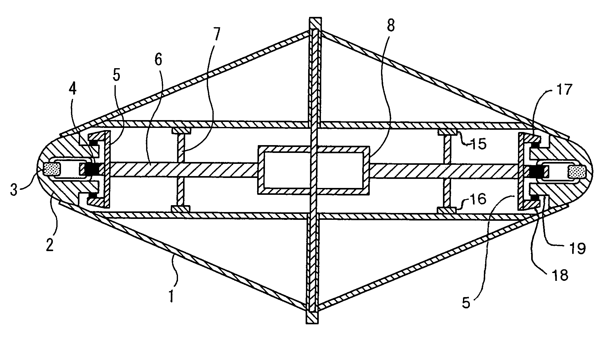
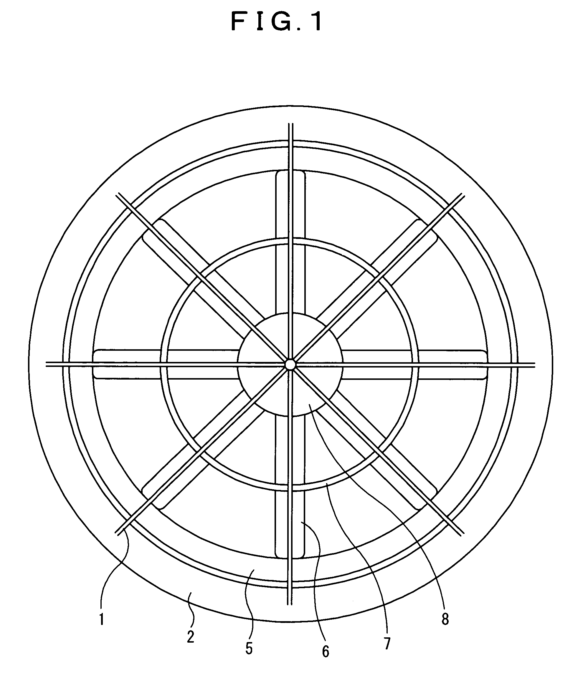
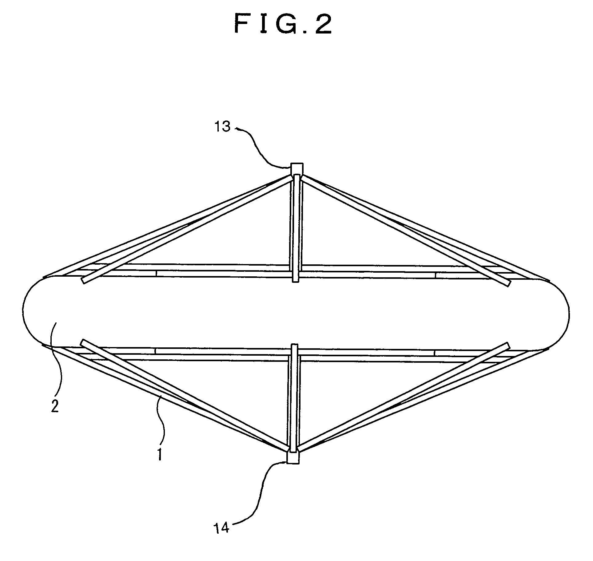
[0029]FIGS. 1 to 8 illustrate a rotatable duct type shrouded rotating wing according to an embodiment of the present invention wherein electromagnets 3 are arranged around the inner periphery of a shroud 2, while permanent magnets 4 are arranged on the outer periphery of a rotatable duct 5, and a rotating magnetic field is generated by the shroud-side electromagnets 3 to rotate the rotatable duct 5 and rotor blades 6, with consequent generation of lift and thrust.

[0030]In the rotating wing, the air speed at mass points thereof increases with distance from the rotational center. Therefore, when the angles of elevation of the rotor blades are the same at any position, the lift at wing tips becomes excessive in comparison with that at the inner wing (blade) ends, resulting in the wing tips being bent upward with rotation of the rotor blades, and the lift against the underlying position decreasing. To avoid this problem, open wing-tip rotor blades used in the recent rotorcrafts are desi...


PUM


Abstract

In a rotatable duct type shrouded rotating wing, permanent magnets are arranged in the outer periphery of a rotatable duct, rotor blades are connected to the inner periphery of the rotatable duct, the rotor blades having a rotatable support portion at about every 2.5 m to prevent deflection or distortion. The shroud and the rotatable duct are constantly in vertical contact with each other, and an appropriate horizontal spacing is provided between the inner periphery of the shroud and the outer periphery of the rotatable duct to permit expansion and contraction of the rotatable duct and the rotor blades. Accordingly, even if the shrouded rotating wing is of a large radius, is used in a horizontal orientation and undergoes a rapid change of direction mounted to a turntable, it always rotates stably to generate lift and thrust.

Description

BACKGROUND OF THE INVENTION[0001]1. Field of Art[0002]The present invention relates to a shrouded rotating wing having an opening of a size exceeding a radius of approximately 3 m and operating based on the principle of a linear motor driving.[0003]2. Background Art[0004]The mechanism of coupling output from a prime mover, such as a turbine positioned near the center of a rotating wing, to a central driving shaft for rotation of the blades, thereby obtaining lift or thrust, has heretofore been used frequently in helicopters and other rotorcrafts. However, the method of making a rotating wing rotate around a shaft defining the central axis of rotation requires a vast amount of energy and thus the efficiency has been low.[0005]Japanese “Kokai” (laid-open application publications) 2001-097288 and H07-205897 disclose a shrouded rotating wing for use as a tail rotor of a single rotor type helicopter. This shrouded rotating wing can rotate blades efficiently and change the rotational spee...

Claims


Application Information

Patent Timeline
Patent Type & Authority Patents(United States)
IPC IPC(8): F04D29/00B64C27/20B64C27/12B64C27/24B64C27/32B64C29/00B64D27/24
CPCB64C27/12B64C27/20B64C27/32B64C29/0016B64D27/24Y02T50/62B64C2201/042B64C2201/108Y02T50/44B64C2201/027Y02T50/60Y02T50/40B64U10/13B64U50/19B64U10/10B64U30/26B64U30/20
Inventor IKEDA, KAIDOU
Owner IKEDA KAIDOU
Why Eureka
Try Eureka