Variable capacity fluid pump for an engine

a fluid pump and variable capacity technology, applied in the direction of positive displacement liquid engines, pumping cylinders, machines/engines, etc., can solve the problems of reducing fuel efficiency, reducing the responsiveness of those mechanisms, and small discharge capacity of the pump, so as to increase or decrease the braking force, the effect of reducing the braking performan

Inactive Publication Date: 2009-03-17
HONDA MOTOR CO LTD
View PDF11 Cites 11 Cited by
  • Summary
  • Abstract
  • Description
  • Claims
  • Application Information

AI Technical Summary

Benefits of technology

[0011]Work of the fluid pump often varies depending on the engine load rather than depending on the engine rotational speed. According to the present invention, the work of the fluid pump can be controlled independently of the engine rotational speed. If the engine is in a condition where requested work of the fluid pump is small, the work of the pump can be actually reduced regardless of the engine rotational speed to improve the fuel efficiency. Since the pump is not electrically driven, the efficiency of converting the engine work to the pump work is high, thereby improving the fuel efficiency.
[0018]According to one embodiment of the present invention, the fluid pump is a water pump. The sensor is a water temperature sensor for detecting a water temperature of the water pump. Alternatively, the sensor is a rotational speed sensor for detecting a rotational speed of the water pump. Since the work of the pump can be reduced by slowing down the water pump when the engine is in a low load condition where the necessity for cooling the engine is low, the fuel efficiency is improved.

Problems solved by technology

There is a problem with a method for driving such fluid pumps (oil pump and water pump) in the lubrication apparatus and the cooling apparatus.
If the engine rotational speed is low, the discharge capacity of the pump is small.
Such a small discharge capacity may reduce the fuel efficiency, especially in the engine having a variable valve driving mechanism and / or a variable compression ratio mechanism because responsiveness of those mechanisms may deteriorate when the engine rotational speed is low.
If the pump is configured to generate a sufficient pump output when the engine rotational speed is low, work by the pump is excessive under the condition where the engine rotational speed is high and the engine load is low.
Such redundant work by the pump reduces the overall engine efficiency.
Although the electrically-driven pump can control a flow rate of the pump independently of the engine rotational speed, there are some problems.
If a brush motor is used, its reliability is low because it is susceptible to aging and failure due to wear of the brush.
If a brushless pump is used, a PDU (power distribution unit) is required for controlling the magnetic field by the three-phase lines, which increases the weight of the pump system and hence decreases the fuel efficiency.

Method used


Image

  • Variable capacity fluid pump for an engine
  • Variable capacity fluid pump for an engine
  • Variable capacity fluid pump for an engine

Examples


Embodiment Construction

1. Variable Capacity Oil Pump

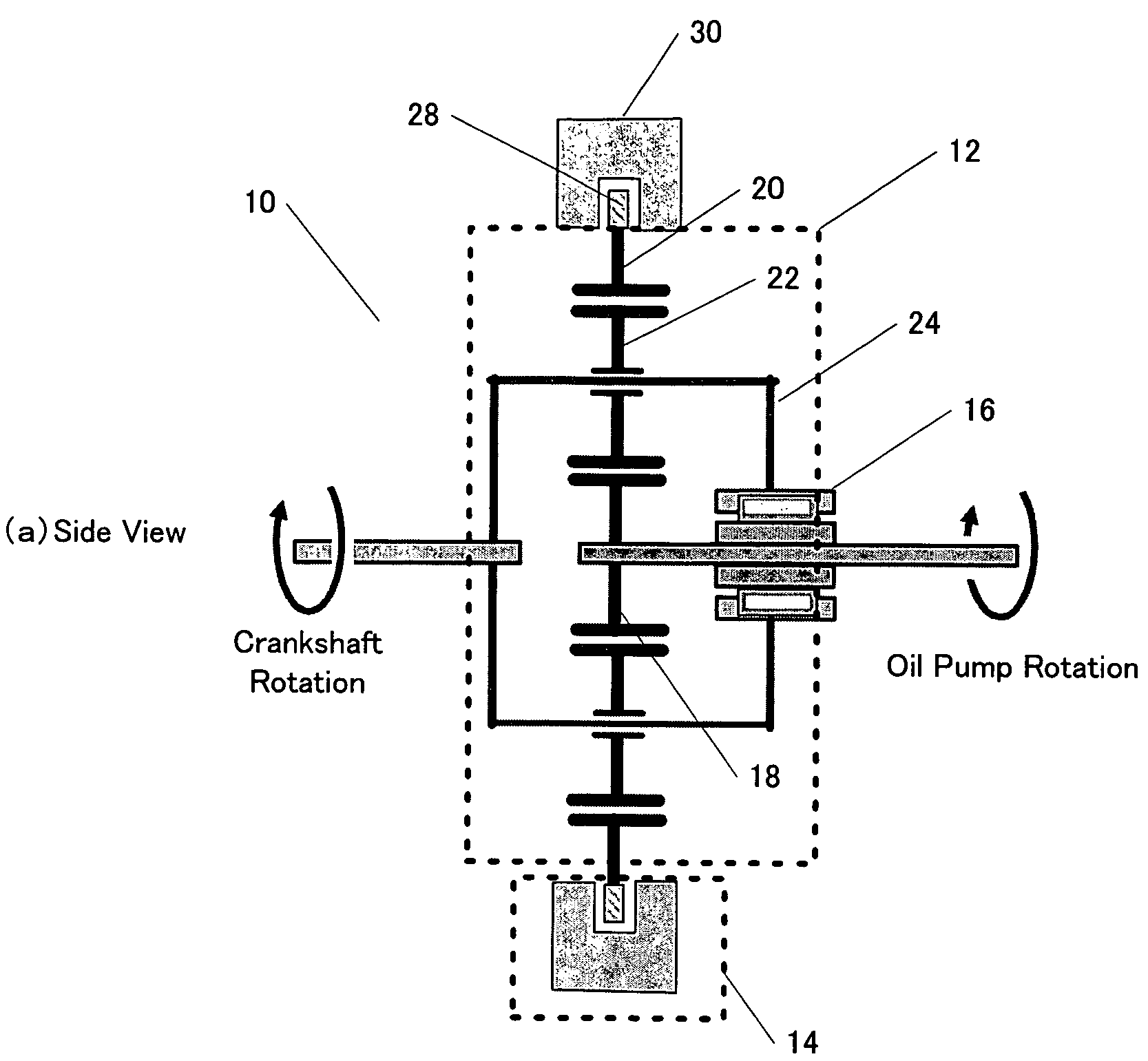
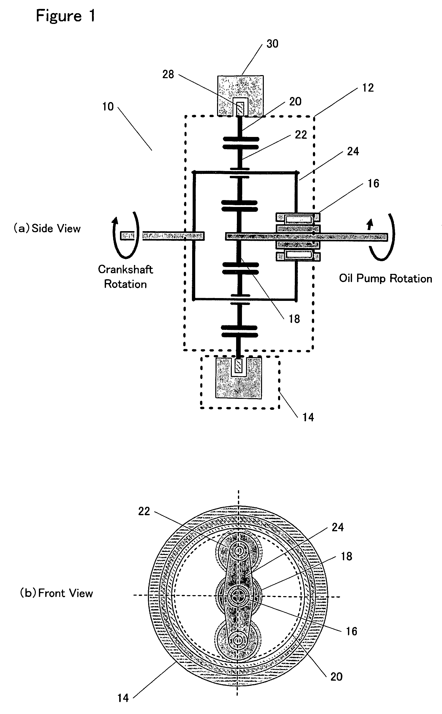
[0030]Referring to the drawings, specific embodiments of the invention will be described. According to one embodiment of the invention, a variable capacity oil pump that is capable of variably controlling the rotational speed of the oil pump with respect to the rotational speed of the engine by disposing a transmission mechanism 10 between a crankshaft of the engine and the oil pump is provided. As shown in FIG. 1, the transmission mechanism includes a planetary gear mechanism 12, a hysteresis brake 14 and a one-way clutch 16.

[0031]The planetary gear mechanism 12 includes a sun gear 18, a ring gear 20 and a plurality of planetary gears 22. The sun gear 21 is connected to the oil pump. The planetary gears are connected to the crankshaft through a carrier 24. The one-way clutch 16 is provided between the sun gear 18 and the carrier 24. The one-way clutch 16 acts so that the direction of a relative rotation of the sun gear 18 with respect to the carrier 24 ...


PUM


Abstract

A variable capacity fluid pump that can be controlled independently of the rotation of the engine is provided. The fluid pump comprises a planetary gear mechanism having a first gear, second gears and a third gear. The second gears are connected to a crankshaft of the engine and transmits a rotational force of the crankshaft. The third gear is connected to the fluid pump. The fluid pump further comprises braking means connected to the first gear. The breaking means generates a braking force upon the first gear. The fluid pump further comprises a one-way clutch provided between the second gears and the third gear. The braking means controls a rotational speed of the first gear so that a rotational speed of the fluid pump is controlled independently of a rotational speed of the crankshaft of the engine.

Description

BACKGROUND OF THE INVENTION[0001]The present invention relates to a control for a fluid pump (an oil pump or a water pump) of an engine.[0002]In general, a lubrication apparatus and a cooling apparatus are supplied with an engine. The lubrication apparatus is an apparatus for reducing the frictional resistance by using oil for each section of the engine. The lubrication apparatus uses an oil pump coupled to a crankshaft of the engine to feed oil to a lubrication passage. The cooling apparatus is an apparatus for keeping the temperature at which the engine can continue rotating with stability. The cooling apparatus feeds cooling water to a passage disposed in a cylinder block and a cylinder head of the engine to prevent the engine from overheating. The cooling apparatus uses a water pump coupled to the crankshaft of the engine to circulate the cooling water. These apparatuses are required for maintaining the engine in the normal operating condition. These apparatuses have an effect o...

Claims


Application Information

Patent Timeline
Patent Type & Authority Patents(United States)
IPC IPC(8): F04B35/00F01M1/02F01M1/16F04C14/24F01P5/12F01P7/14F01P7/16F02B67/04F04B49/00F04D13/02
CPCF01M1/16F01P5/12F01P7/164F01P7/167F02B67/04F04D13/028F01M2001/0253F01M2001/0269F16N2250/04
Inventor YASUI, YUJI
Owner HONDA MOTOR CO LTD
Why Eureka
Try Eureka