Plasma processing apparatus and plasma processing method

a processing apparatus and plasma technology, applied in the field of plasma processing apparatus and plasma processing method, can solve the problem of not progressing etching, and achieve the effect of preventing failure of chucking the wafer and lowering the pressur

Inactive Publication Date: 2009-03-17
TOKYO ELECTRON LTD
View PDF23 Cites 75 Cited by
  • Summary
  • Abstract
  • Description
  • Claims
  • Application Information

AI Technical Summary

Benefits of technology

[0010]With this structure, the plasma discharge can be maintained only by controlling the first radio-frequency power, so that the control can be simplified.
[0026]This structure makes it possible to lower the pressure given to the back face of the wafer before the chucking of the wafer is stopped, so that failure in chucking the wafer can be prevented.

Problems solved by technology

Consequently, even when the application of the direct-current voltage to the electrostatic chuck is stopped with the plasma discharge being maintained, etching does not further progress after the completion of the plasma processing, which makes it possible to stop the application of the direct-current voltage while inhibiting the adhesion of particles to the wafer.

Method used


Image

  • Plasma processing apparatus and plasma processing method
  • Plasma processing apparatus and plasma processing method
  • Plasma processing apparatus and plasma processing method

Examples


Embodiment Construction

[0032]Hereinafter, a plasma processing apparatus according to embodiments of the present invention will be explained with reference to the drawings.

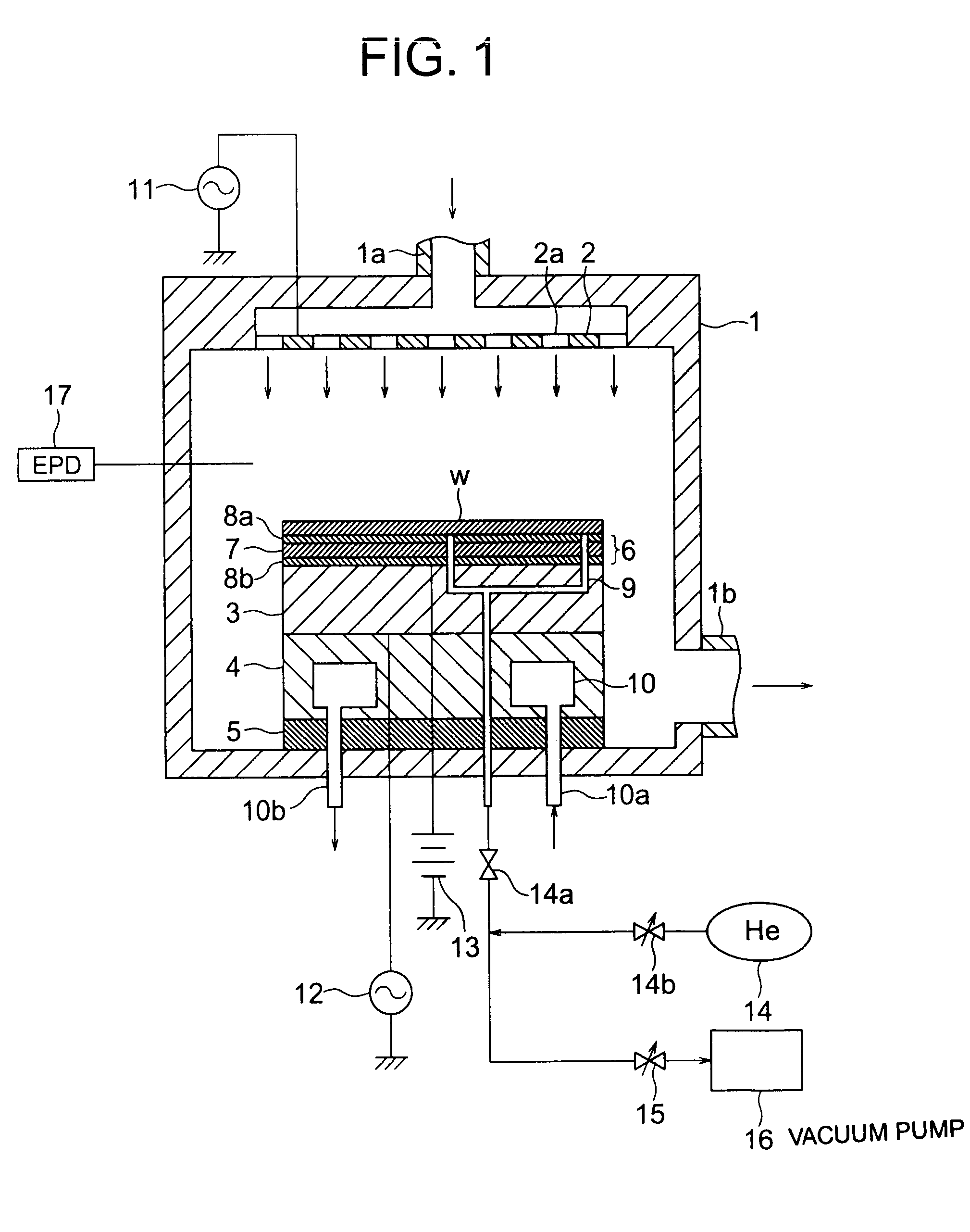
[0033]FIG. 1 is a cross sectional view showing the schematic configuration of a plasma processing apparatus according to an embodiment of the present invention. In FIG. 1, a top electrode 2 and a susceptor 3 are provided in a process chamber 1, and this susceptor 3 also serves as a bottom electrode. Gas blowout ports 2a through which an etching gas is introduced into the process chamber 1 are provided in the top electrode 2. The susceptor 3 is supported on a susceptor supporting table 4 and the susceptor supporting table 4 is held in the process chamber 1 via an insulating plate 5. Further, radio-frequency power sources 11, 12 are connected to the top electrode 2 and the susceptor 3 respectively to plasmatize the etching gas introduced into the process chamber 1. A main function of the top electrode 2 is to ionize gas molecules introduce...


PUM

PropertyMeasurementUnit
frequencyaaaaaaaaaa
pressureaaaaaaaaaa
RF poweraaaaaaaaaa

Abstract

An RF power (Bottom RF) from a radio-frequency power source 12 is turned off (t5) and the supply of a He gas 14 to a back face of a wafer W is stopped (t5) when an end point detector 17 (EPD) detects an end point (t5), and a high-voltage DC power source 13 (HV) is turned off (t6) under the condition in which an RF power (Top RF) from a radio-frequency power source 11 is controlled to fall within a range in which etching does not progress and plasma discharge can be maintained (t5). This process enables the inhibition of the adhesion of particles while an etching amount is accurately controlled.

Description

CROSS REFERENCE TO RELATED APPLICATION[0001]This application is related to and claims priority to U.S. Ser. No. 10 / 469,235 under 35 U.S.C. § 121, the entire contents of which are incorporated herein by reference. This application is also related to PCT Application PCT / JP02 / 02007, the entire contents which are incorporated herein by reference.TECHNICAL FIELD[0002]The present invention relates to a plasma processing apparatus and a plasma processing method, more particularly, to those suitable for use when an RF power is applied to a top and a bottom electrode.BACKGROUND ART[0003]Some conventional plasma processing apparatus use an electrostatic chuck in order to fix a wafer in a chamber. In a method using this electrostatic chuck, a high DC voltage is applied to the electrostatic chuck to cause a Coulomb force to act on the wafer, thereby fixing the wafer.[0004]In such a plasma processing apparatus, the application of the high DC voltage to the electrostatic chuck under the condition...

Claims


Application Information

Patent Timeline
Patent Type & Authority Patents(United States)
IPC IPC(8): B05D1/04H05H1/46B01J19/08B05D1/08H01J37/32H01L21/302H01L21/3065H01L21/311H01L21/3213H01L21/68H01L21/683H05H1/26
CPCH01J37/32082H01J37/32935H01L21/31116H01L21/32137H01L21/3065
Inventor IIJIMA, ETSUOTSUCHIYA, HIROSHI
Owner TOKYO ELECTRON LTD
Why Eureka
Try Eureka