Security system and monitoring method using power line communication technology

a technology of communication technology and security system, applied in powerline communications applications, frequency-division multiplexes, instruments, etc., can solve the problem of low versatility and achieve the effect of high versatility

Inactive Publication Date: 2009-03-17
FUNAI ELECTRIC CO LTD
View PDF14 Cites 130 Cited by
  • Summary
  • Abstract
  • Description
  • Claims
  • Application Information

AI Technical Summary

Benefits of technology

[0011]Accordingly, a main object of the present invention is to provide a security system and a monitoring method that are less likely to be noticed by an intruder and have high versatility.
[0018]As such, according to the present invention, when the pressure value output from the pressure sensor portion fluctuates, the prescribed party is notified that the abnormal event is sensed. The pressure sensor portion for sensing the intrusion of a suspicious person is mounted on a general household electrical appliance such as a carpet, and hence is less likely to be noticed by the intruder. Furthermore, by using a power line communication technology, it is possible to implement a security system and a monitoring method that have high versatility.

Problems solved by technology

However, it is necessary to connect the personal computer installed inside the building to the Internet, resulting in low versatility.

Method used


Image

  • Security system and monitoring method using power line communication technology
  • Security system and monitoring method using power line communication technology
  • Security system and monitoring method using power line communication technology

Examples


first embodiment

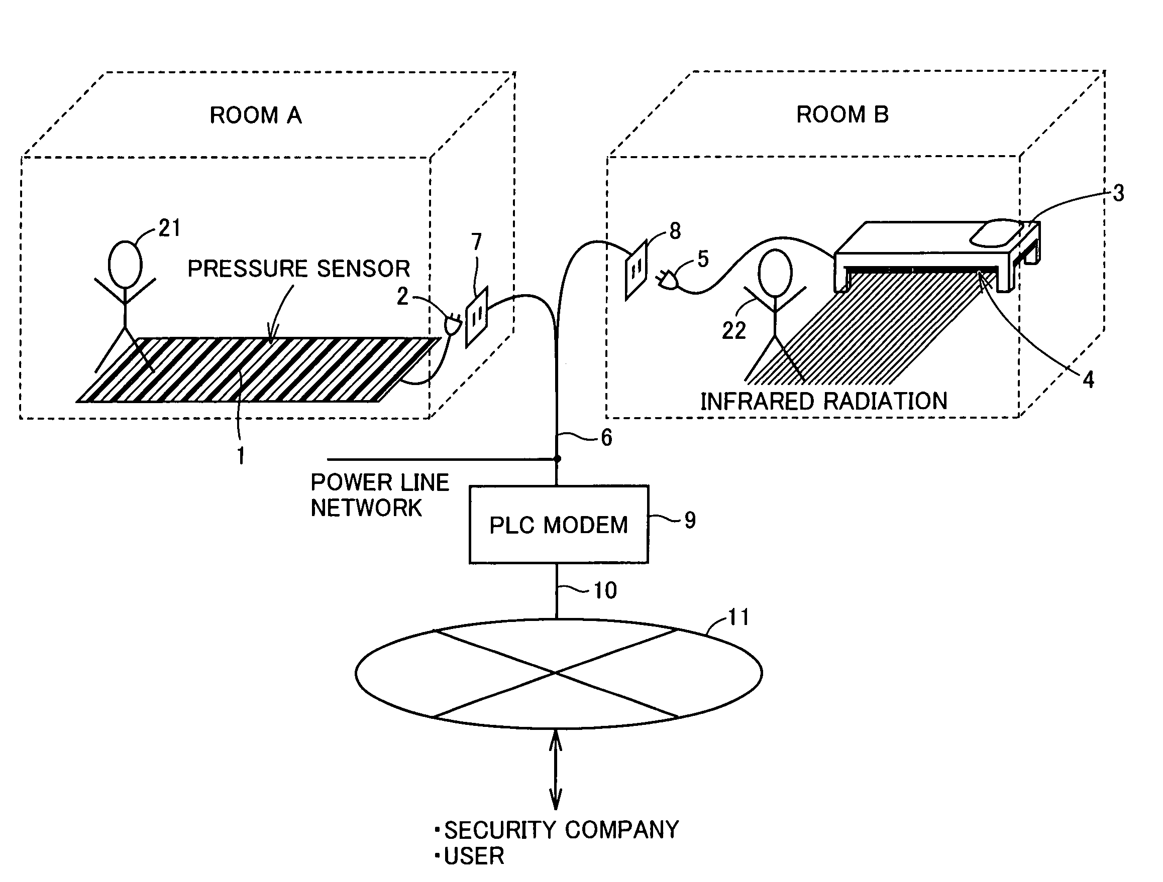
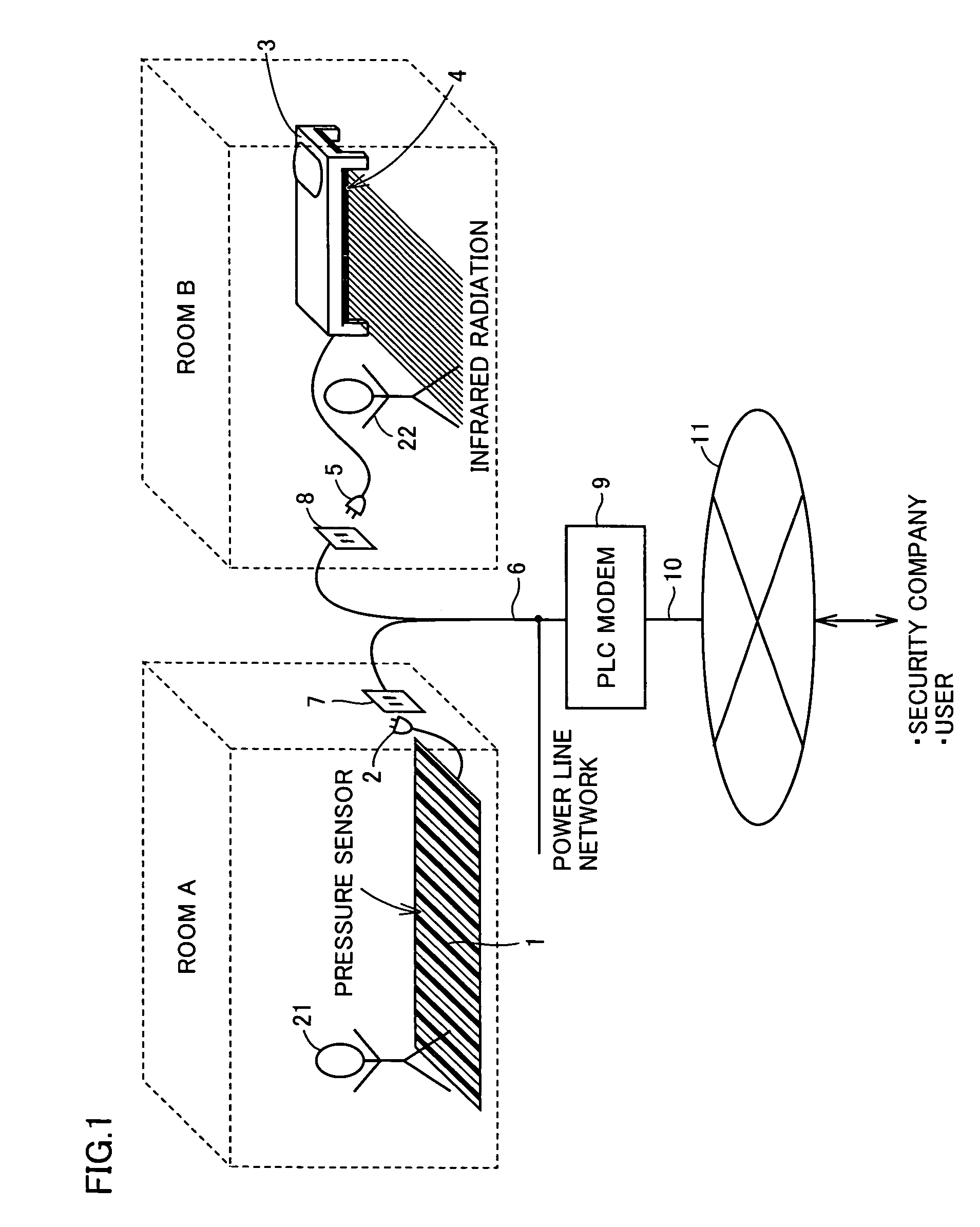
[0032]FIG. 1 is a block diagram showing a schematic configuration of a security system according to a first embodiment of the present invention. In FIG. 1, the security system includes a pressure-sensor-equipped carpet 1, a power supply plug 2 connected to pressure-sensor-equipped carpet 1, a bed 3, an infrared radiation sensor 4 installed at a lower portion of bed 3, a power supply plug 5 connected to infrared radiation sensor 4, a power line 6 connected to a power line network, receptacles 7, 8 connected to power line 6, and a PLC modem 9 connected to power line 6. PLC modem 9 is connected to a communication network 11 through a communication cable 10.

[0033]Pressure-sensor-equipped carpet 1, power supply plug 2, and receptacle 7 are installed in a room A. Bed 3, infrared radiation sensor 4, power supply plug 5, and receptacle 8 are installed in a room B. Power line 6 is an electricity distribution line for supplying power to each of the rooms. In the power line communication, powe...

second embodiment

[0049]FIG. 6 is a block diagram showing a schematic configuration of a security system according to a second embodiment. Referring to FIGS. 6 and 1, the security system according to the second embodiment uses a pressure-sensor-equipped carpet 1A instead of pressure-sensor-equipped carpet 1. On this point, the configuration of the security system according to the first embodiment is different from that of the security system according to the second embodiment. Other portions of the security system shown in FIG. 6 are similar to corresponding portions of the security system shown in FIG. 1, and hence the description thereof will not be repeated.

[0050]A single pressure value or a plurality of pressure values is / are registered with pressure-sensor-equipped carpet 1A in advance. Pressure-sensor equipped carpet 1A outputs a data signal indicating that an abnormal event is sensed if a value of the pressure actually applied to the surface thereof does not fall within a prescribed range.

[005...

third embodiment

[0060]FIG. 10 is a block diagram showing a schematic configuration of a security system according to a third embodiment. Referring to FIGS. 10 and 6, a pressure-sensor-equipped carpet 1B is provided at an entrance in the security system according to the third embodiment. On this point, a configuration of the security system according to the second embodiment is different from that according to the third embodiment. Other portions of the security system shown in FIG. 10 are similar to corresponding portions of the security system shown in FIG. 6, and hence the description thereof will not be repeated.

[0061]Furthermore, the internal configuration of pressure-sensor-equipped carpet 1B shown in FIG. 10 is similar to that of pressure-sensor-equipped carpet 1A shown in the block diagram of FIG. 7, and hence the description thereof will not be repeated.

[0062]In the case of the security system according to the second embodiment, there is a probability that an abnormal event is also sensed i...


PUM


Abstract

A pressure sensor portion includes a plurality of pressure sensors arranged in a plurality of rows and a plurality of columns inside a pressure-sensor-equipped carpet. The pressure sensor portion senses a pressure applied to the surface thereof and outputs a pressure value to a control portion. In an initial learning mode, a storage portion stores, as an initial value, the pressure value output from the pressure sensor portion. In a sensing operation mode, the control portion outputs to a modem portion a data signal indicating that an abnormal event is sensed, when the pressure value output from the pressure sensor portion is larger than the initial value stored in the storage portion by at least a prescribed threshold value. The modem portion superimposes the data signal received from the control portion on a power carrier wave (with a frequency of 50-60 Hz) and outputs the data signal to a power supply plug.

Description

BACKGROUND OF THE INVENTION[0001]1. Field of the Invention[0002]The present invention relates to a security system and a monitoring method, and particularly relates to a security system and a monitoring method that use a power line communication technology utilizing a power line to provide data communication.[0003]2. Description of the Background Art[0004]A Power Line Communication (PLC) technology, which can utilize an existing power line to provide data communication, superimposes a data signal with a high frequency (e.g. 10-450 kHz) on a power carrier wave (50-60 Hz) on a power line of a commercial power supply, to provide data communication. If a frequency band allocated to the data signal is extended to further enhance the speed of data communication, connectivity to the Internet can also be provided by the use of a power line. The use of the power line communication technology has such an advantage as to allow data communication from any room as long as a power receptacle is i...

Claims


Application Information

Patent Timeline
Patent Type & Authority Patents(United States)
IPC IPC(8): G08B1/08G01G23/18G08B21/00H04M11/04
CPCG08B13/10G08B25/06H04B3/54H04B2203/5416H04B2203/542H04B2203/5458
Inventor EIZA, TSUYOSHI
Owner FUNAI ELECTRIC CO LTD
Why Eureka
Try Eureka