Order-independent 3D graphics binning architecture

a 3d graphics and order-independent technology, applied in the field of computer graphics, can solve the problems of large data manipulation to be done, large memory bandwidth, and large geometry to be added, so as to add complexity, add visual interest to a scene, and improve frame rate

Active Publication Date: 2009-03-17
XUESHAN TECH INC
View PDF4 Cites 113 Cited by
  • Summary
  • Abstract
  • Description
  • Claims
  • Application Information

AI Technical Summary

Benefits of technology

[0010]There are different ways to add complexity to a 3D scene. Creating more and more detailed models, consisting of a greater number of polygons, is one way to add visual interest to a scene. However, adding polygons necessitates paying the price of having to manipulate more geometry. 3D systems have what is known as a “polygon budget,” an approximate number of polygons that can be manipulated without unacceptable performance degradation. In general, fewer polygons yield higher frame rates.
[0011]The visual appeal of computer graphics rendering is greatly enhanced by the use of “textures”. A texture is a two-dimensional image which is mapped into the data to be rendered. Textures provide a very efficient way to generate the level of minor surface detail which makes synthetic images realistic, without requiring transfer of immense amounts of data. Texture patterns provide realistic detail at the sub-polygon level, so the higher-level tasks of polygon-processing are not overloaded. See Foley et al., Computer Graphics: Principles

Problems solved by technology

However, even after these transformations and extensive calculations have been done, there is still a large amount of data manipulation to be done: the correct values for EACH PIXEL of the transformed polygons must be derived from the two-dimensional representation.
The most challenging 3D graphics applications are dynamic rather than static.
However, adding polygons necessitates paying the price of having to manipulate more geometry.
Achieving an adequately high rate of texturing and fill operations requires a very large memory bandwidth.
There may be no correct rendering order when transparent primitives are cyclically interleaved or penetrated, and in the

Method used


Image

  • Order-independent 3D graphics binning architecture
  • Order-independent 3D graphics binning architecture
  • Order-independent 3D graphics binning architecture

Examples


Embodiment Construction

[0055]The numerous innovative teachings of the present application will be described with particular reference to the presently preferred embodiment (by way of example, and not of limitation).

[0056]Order—Independent 3D Graphics Binning Architecture

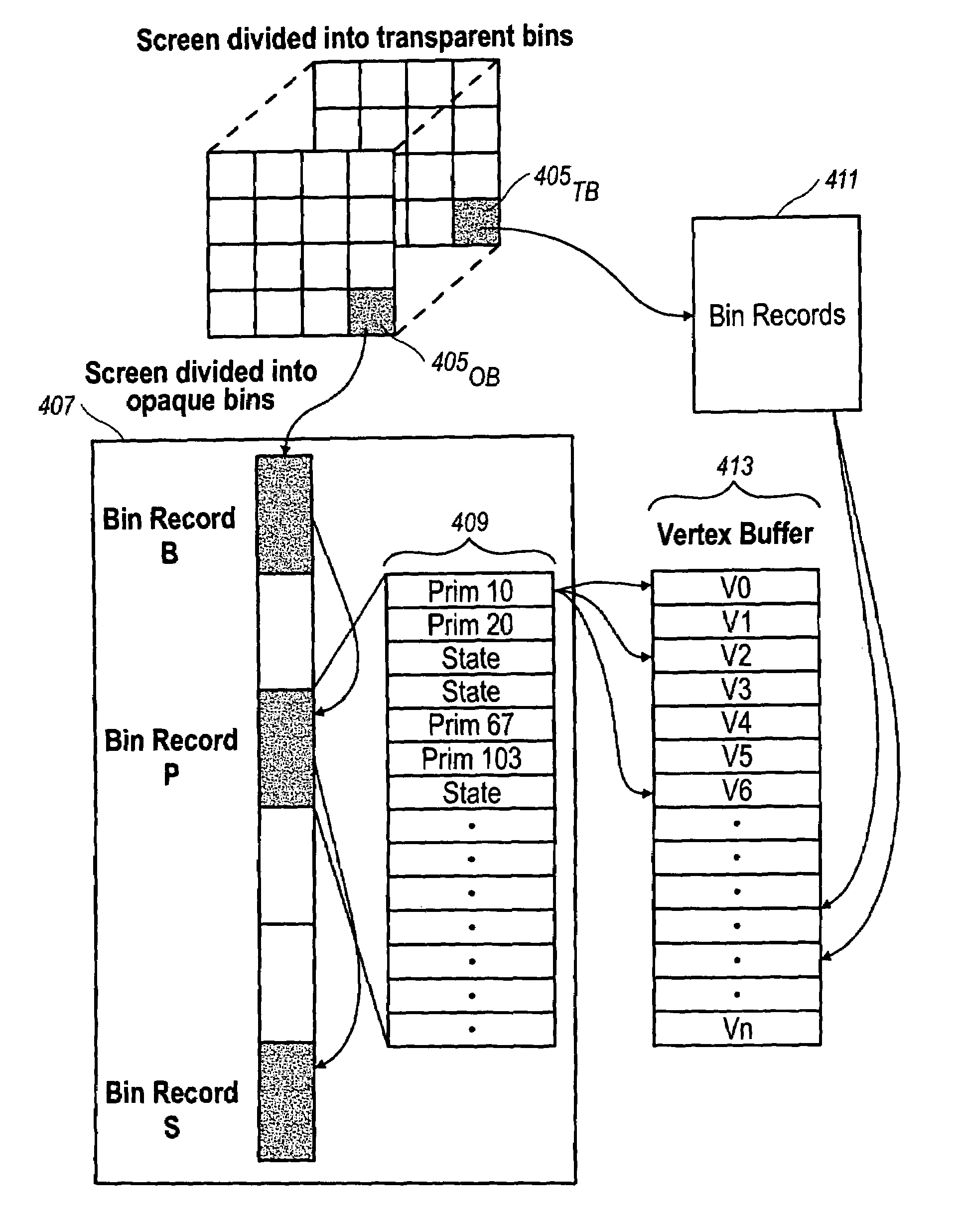
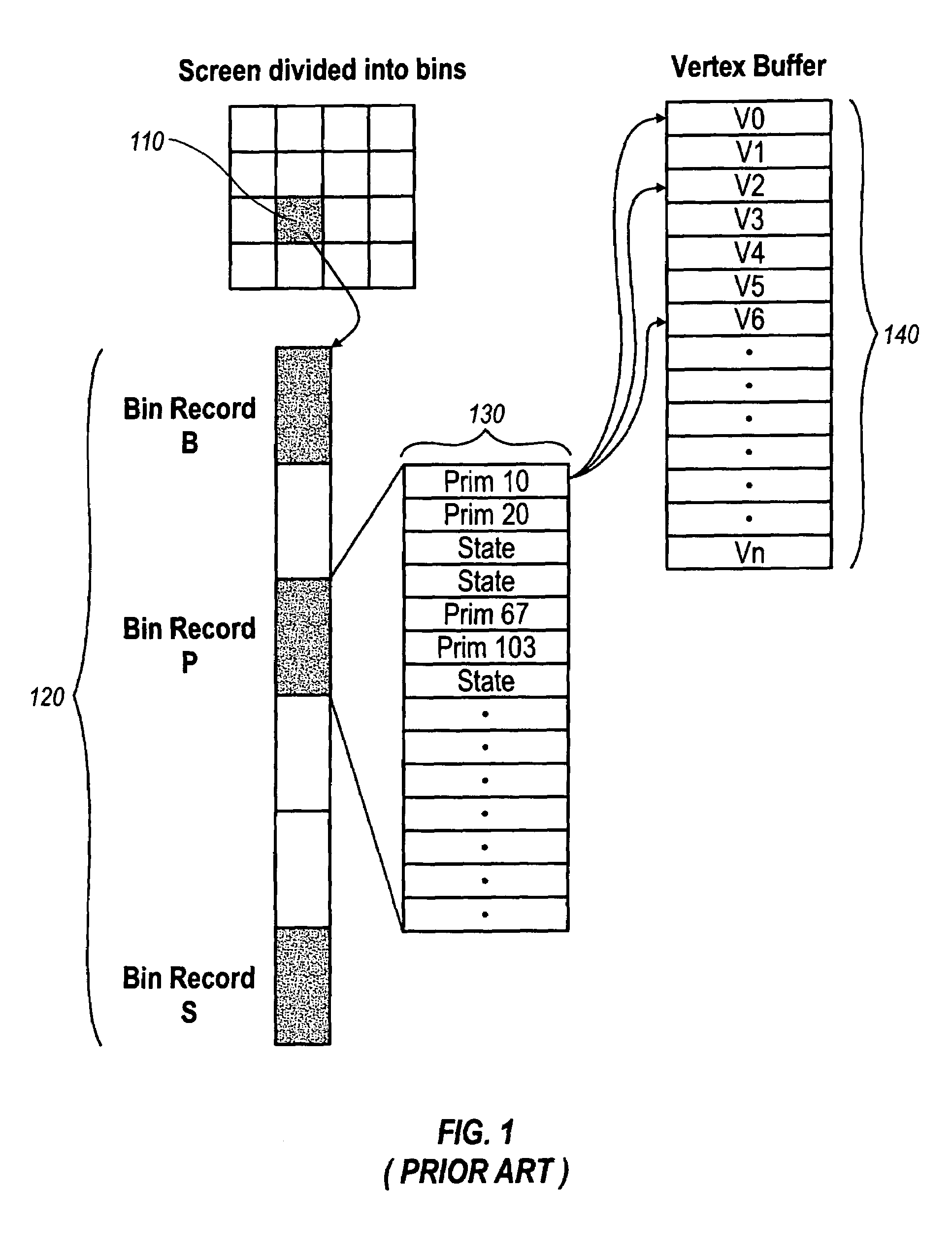
[0057]FIG. 1 depicts a screen divided into bins utilizing a conventional binning method. As shown in this figure, bin 110 holds the information for both transparent and opaque primitives. List 120 shows a sample embodiment of the bin records associated with bin 110. List 130 shows a sample embodiment of the information associated with bin record p. Vertex buffer 140 shows a sample embodiment of a vertex buffer and its correlation to the vertices associated with primitive 10 of bin record p.

[0058]FIG. 2 is a flowchart of the bin build phase of a conventional binning method. This involves waiting for a new command (step 210). Once a new command is received, the system must determine if it is a new frame that is called for (step 220).

[0059]If...


PUM


Abstract

A binning architecture that allows opaque and transparent primitives to be segregated automatically into pairs of bins covering the same bin rectangle on the screen. When the frame is complete, the opaque bin will be rendered first and then the transparent bin will be rendered repeatedly using the depth peeling algorithm until all the layers have been resolved. This will happen automatically without requiring the application to isolate and store the transparent primitives until all of the opaque primitives have been rendered or submit the transparent primitives repeated until all of the transparent layers have been resolved.

Description

FIELD OF THE INVENTION[0001]The present inventions relate to computer graphics and, more particularly, to a computer graphics rendering architecture that segregates transparent primitives from opaque primitives prior to rendering.BACKGROUND AND SUMMARY OF THE INVENTION[0002]Background: 3D Computer Graphics[0003]One of the driving features in the performance of most single-user computers is computer graphics. This is particularly important in computer games and workstations, but is generally very important across the personal computer market.[0004]For some years, the most critical area of graphics development has been in three-dimensional (“3D”) graphics. The peculiar demands of 3D graphics are driven by the need to present a realistic view, on a computer monitor, of a three-dimensional scene. The pattern written onto the two-dimensional screen must, therefore, be derived from the three-dimensional geometries in such a way that the user can easily “see” the three-dimensional scene (a...

Claims


Application Information

Patent Timeline
IPC IPC(8): G06T15/40G06F13/00G06T15/00G06T15/50
CPCG06T15/503G06T2200/28G06T2210/62
Inventor BALDWIN, DAVID
Owner XUESHAN TECH INC
Why Eureka
Try Eureka