
Performance monitoring in a communications network

a technology for communications networks and processors, applied in data switching networks, frequency-division multiplexes, instruments, etc., can solve problems such as alarm flood or surge, alarm multiplexing, and faults on all paths multiplexed on that link, and achieve the effect of reducing the amount of memory required to store records

Active Publication Date: 2009-03-17
CIENA
View PDF9 Cites 15 Cited by
  • Summary
  • Abstract
  • Description
  • Claims
  • Application Information

AI Technical Summary

Benefits of technology

The present invention provides a method and apparatus for monitoring performance in a communications network by allocating signal quality characterizations to signals and identifying time intervals of constant quality. These records can be easily manipulated to reduce memory usage while maintaining accuracy. The time intervals are defined as the time between signal quality characterization changes, and each record includes the length of the interval and the signal quality characterization. The invention allows for efficient and accurate monitoring of performance in real-time, and can be used in network elements of the communications network. The records can be used for generating a performance log, which is a chronological record of the signal quality characterizations.

Problems solved by technology

Where many communications paths are multiplexed onto a link of the network, when a fault occurs on the link of the network, faults may occur on all of the paths multiplexed on that link.
If path alarms are raised when a path fault occurs, then a fault on a link will generate many such alarms.
This results in alarm floods or surges when a fault occurs on the network and this can impact the DCN and impair the performance of management platforms, such as a management platform responsible for processing alarm reports.
Firstly, the 15 minute and 24 hour reports are still collected even if there are no defects for the period. So over an error free period a total of 96 15 minute reports and 1 24 hour report will be collected. In this circumstance the PM report log is not succinct.
Secondly, if over a period a small number of defects are detected, it is not easy to see at a glance what periods of continuous defect free time were enjoyed by a given path. In this case the 24 hour report will contain a small number of defects as will some of the 15 minute reports so that continuous defect free time has to be pieced together from defect free 15 minute reports. The 24 hour report does not have the granularity required, although it is concise, given the period it covers. The 15 minute reports, have improved granularity, although not sufficient to determine exactly when a service may have failed. The 15 minute reports have the added disadvantage that it requires larger amounts of memory to store them.
Thirdly, the precise time that a defect occurred is not known beyond the granularity of the report. For example if a 15 minute report counts several ESs, it is not known when in the 15 minute period they occurred or whether the ESs occurred together or at different times. Precise time can be important in assessing whether a service outage breaches the conditions set out in a service level agreement.
Firstly, logs are typically stored in non-volatile memory so that the log can be recovered even after a power loss on a network element. The available memory for logs is typically limited within a network element. A goal is that it should be possible to store 24 hours of defect activity in a log. The amount of memory required to store 24 hours of defect activity varies dependant on the stability of the network. However, it is generally accepted that log memory is unlikely to last 24 hours before information is lost by new text log entries overwriting old ones.
Secondly, when troubleshooting a rapidly toggling defect, a log containing hundreds (even thousands) of alternating defect raised, defect cleared entries does not help in detailing service performance. The likelihood is that entries in the log of important information, for example indicating the first onset of the defect, will be lost as a result of new text log entries overwriting old ones.

Method used


Image

  • Performance monitoring in a communications network
  • Performance monitoring in a communications network
  • Performance monitoring in a communications network

Examples


Embodiment Construction

[0078]There will now be described by way of example the best mode contemplated by the inventor for carrying out the invention. In the following description, numerous specific details are set out in order to provide a complete understanding of the present invention. It will be apparent, however, to those skilled in the present invention may be put into practice with variations of the specific.

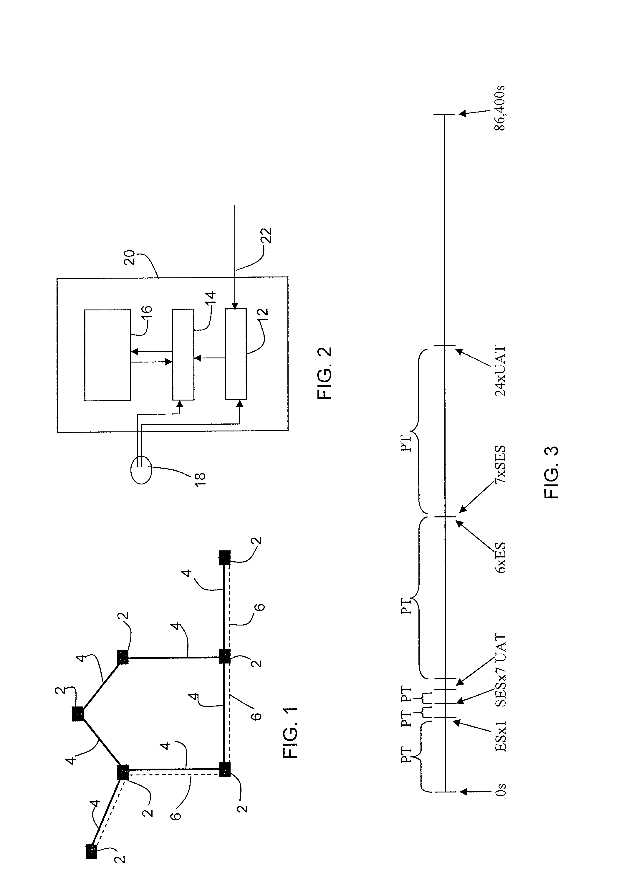
[0079]FIG. 1 shows a portion of a communications network comprising a plurality of network elements (2, 2′) connected by communication links (4). The links may comprise radio frequency links, optical links or electrical links for carrying signals between the network elements. The communication links (4) shown schematically in FIG. 1 may carry signals between network elements in both directions. The communications network is managed by a network management system (not shown) with which some or all of the network elements (2, 2′) communicate. Many signals may be multiplexed onto each link (4) so t...


PUM


Abstract

A method of performance monitoring and a processor for performance monitoring in a communications network are provided. A signal is monitored over time by allocating a current signal quality characterization to the signal, selected from at least two such signal quality characterizations, such as perfect time, errored time and unavailable time. A plurality of time intervals making up a continuous succession of such time intervals are identified, such that a current time interval is terminated and a next time interval is initiated each time the signal quality characterization allocated to the signal changes. Then, a record of each identified time interval is generated and can be used to generate a performance log. Selected records may be manipulated to reduce the amount of memory required to store the records while intelligently degrading their accuracy.

Description

FIELD OF THE INVENTION[0001]This invention relates to a method of and a processor for monitoring the performance of a communications network in particular so as to generate a performance log with a rich information content.BACKGROUND OF THE INVENTION[0002]A communications network generally comprises a plurality of network elements connected by links, for example optical links or radio links. The communications network may carry many communications paths between end users of the network, with a plurality of communications paths multiplexed onto single links of the network. A communications network is generally managed by an operator at an Operations Centre (OC) site remote from the communications network through a Data Communications Network (DCN) and performance monitoring of the links of the network may be carried out at elements of the network with the elements of the network reporting the results of performance monitoring on the DCN. In this way faults on the links can be identif...

Claims


Application Information

Patent Timeline
Patent Type & Authority Patents(United States)
IPC IPC(8): H04L12/26G06F11/00H04L12/24
CPCH04L43/08H04L43/0823H04L41/5003H04L41/5009H04L41/5032
Inventor MURGATROYD, COLINRAMSDEN, CHRIS
Owner CIENA
Learn More