Split radiator maximizing entering temperature differential

a radiator and temperature differential technology, applied in the field of radiators, can solve the problems of long time to recapture the cost of efficiency savings through efficiency savings, increase the cost of tooling, and the inability to achieve the effect of increasing the coefficient of heat transfer

Inactive Publication Date: 2009-03-24
IEA
View PDF6 Cites 1 Cited by
  • Summary
  • Abstract
  • Description
  • Claims
  • Application Information

AI Technical Summary

Benefits of technology

[0019]According to a still further advantage yet, the baffles segregate the coolers from each other. One component of the air flow of axial fans moves radially from the fan (the other component is the axially linear movement) and generally parallel to the front of the coolers. The baffles prevent the radial motion of the air from sweeping between coolers and transferring heat between the coolers and passing through the heat exchanger at the point of least resistance.

Problems solved by technology

While these improvements are quantifiable and generally useful, there are limitations (both practical and theoretical) as to how much the coefficient of heat transfer can be improved.
For example, the increased tooling costs may overshadow any savings associated with the increased coefficient.
Accordingly, it may take a long time to recapture those costs through efficiency savings, if it is even possible at all.
There are several drawbacks associated with such standard arrangements.
The fan therefore needs to have greater horsepower capacity (i.e. higher initial cost plus increased energy consumption during operation) in order to move the intended amount of air through the heat exchanger to overcome the increase in system pressure.
A further drawback of such an arrangement is that the ambient air first passes through the charge air cooler, and then passes through the jacket water cooler.
Such a design is disadvantageously engineered to be less than optimally efficient.
A still further drawback of the stacked system is that for dual turbocharged engines, a manifold is required to route the charge air through the charge air cooler.
First, it would be undesirable if the return manifold did not evenly distribute the cooled charge air back to both sides of the engine.
Second, the charge air can suffer from a pressure loss as it passes through the torturous paths of the manifold and other required piping.
Pressure loss of the charge air during routing to and from the charge air cooler reduces the net effect of the turbochargers.
Third, the piping and plumbing can add to the overall complexity of the design and manufacturing of the heat exchanger, and the piping and plumbing can be inconvenient to access.
It is well know that axial fans have a “dead” spot where the hub rotates due to the lack of air being driven.
Non-uniform air flow rates in an axial direction are caused by the “dead” spots.
The standard stacked arrangement prohibits mechanical compensation for different air flow rates across the front face of the heat exchanger due to the dead spot.
Accordingly, some portions of the heat exchanger are capable at operating at higher efficiency relative the other portions making the overall heat transfer efficiency less than ideal.

Method used


Image

  • Split radiator maximizing entering temperature differential
  • Split radiator maximizing entering temperature differential
  • Split radiator maximizing entering temperature differential

Examples


Embodiment Construction

[0029]While the invention will be described in connection with several preferred embodiments, it will be understood that it is not intended to limit the invention to those embodiments. On the contrary, it is intended to cover all alternatives, modifications and equivalents as may be included within the spirit and scope of the invention as defined by the appended claims.

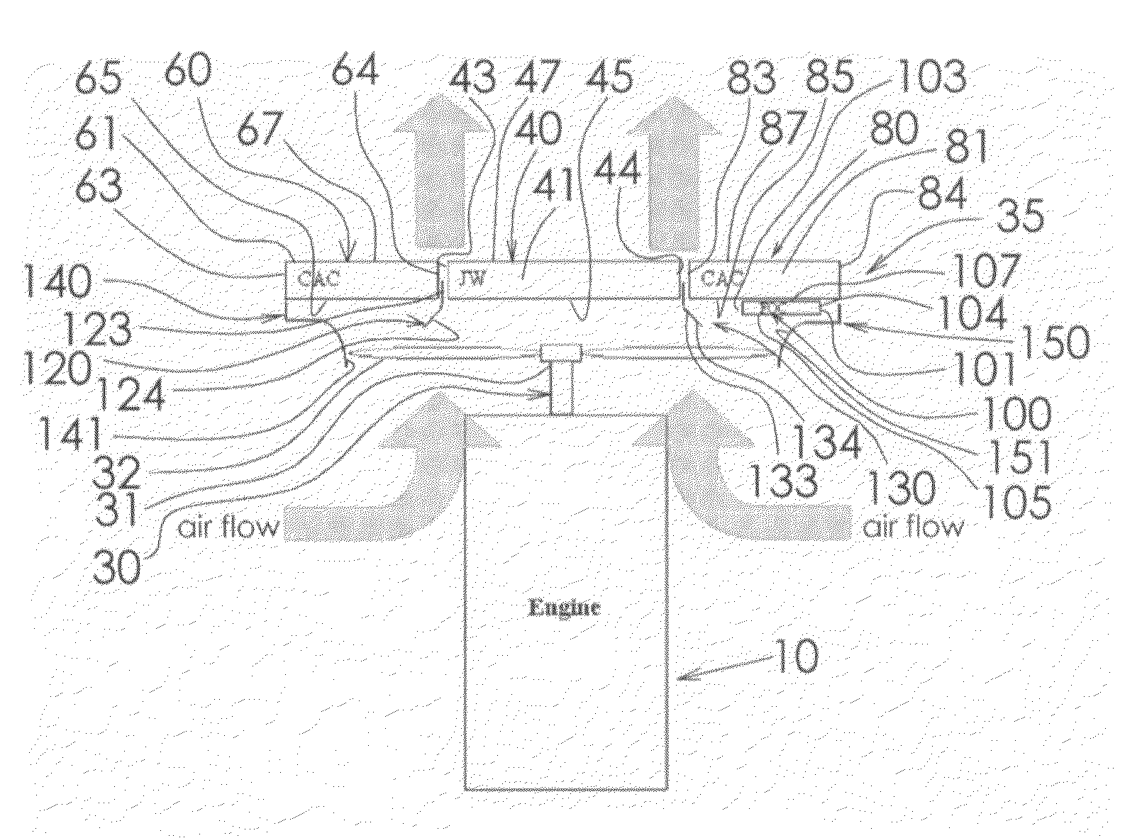
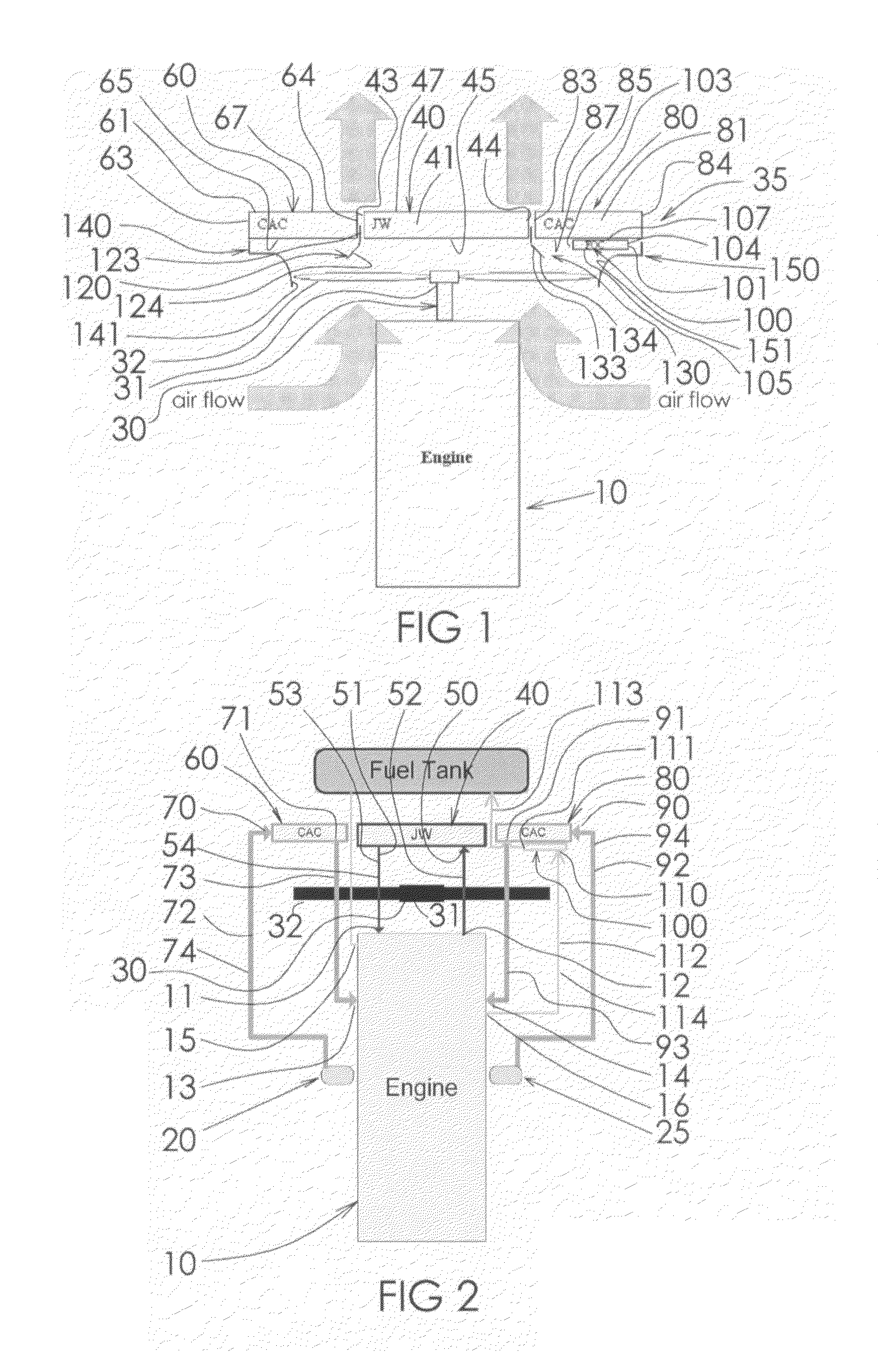
[0030]The present invention is intended for use with an engine 10 designed for use with two turbochargers 20 and 25, respectively. Preferably, the engine 10 is a stationary engine. Yet, it is understood that the principals of the present invention could be applied to mobile engines. It is further understood that in a forced convection application, the mechanical air mover or fan may be unnecessary. The engine 10 has a coolant inlet 11 and a coolant outlet 12. The engine 10 further has a first charge air inlet 13 and a second charge air inlet 14. The charge air inlets 13 and 14 are preferably on opposed sides of the en...


PUM


Abstract

A heat exchanger is provided for dissipating heat from a dual turbocharged engine. The heat exchanger has a jacket water cooler, and first and second charge air coolers. The three coolers are arranged in parallel enabling each to operate with a maximum temperature differential, and have fronts that lie in parallel planes. Charge air from a first turbocharger is directly piped to the first charge air cooler, and charge air from the second turbocharger is directly piped to the second charge air cooler. A first baffle is between and upstream of the first charge air cooler and the jacket water cooler. A second baffle is between and upstream of the second charge air cooler and the jacket water cooler. The baffles can direct selected amounts of air to each of the three coolers and prevent radial convective scrubbing. A fuel oil cooler can also be provided.

Description

BACKGROUND OF THE INVENTION[0001]1. Field of the Invention[0002]The present invention relates to a split heat exchanger, and particularly to a radiator with maximized entering temperature differentials for both at least one charge air cooler and a jacket water cooler.[0003]2. Description of the Related Art[0004]It is well known that heat energy contained in one fluid is capable of being transferred to another fluid. Such heat transfer is described in the classical heat transfer equation: Q=UAdT. In this equation, Q represents the heat transfer, U represents a coefficient of heat transfer, A represents the surface area through which the heat can be transferred, and dT represents the change in temperatures between the two mediums. Heat exchangers, and radiators in particular, are designed for a relative high level of transfer of heat energy from one medium to another. One common example is an automobile radiator, in which a coolant fluid passes through an engine to absorb heat energy ...

Claims


Application Information

Patent Timeline
Patent Type & Authority Patents(United States)
IPC IPC(8): F01P1/06
CPCF01P3/20F01P11/10F01P2060/02F01P2060/04
Inventor MEISSNER, ALAN PAULCHRISTENSON, JEFFREY J.CHARTRAND, RANDALL LEEMOTL, DENNIS MICHAEL
Owner IEA
Why Eureka
Try Eureka