Failure detection apparatus for an alternator

Active Publication Date: 2009-03-24
MITSUBISHI ELECTRIC CORP
View PDF4 Cites 13 Cited by
  • Summary
  • Abstract
  • Description
  • Claims
  • Application Information

AI Technical Summary

Benefits of technology

[0009]According to the present invention, by performing a failure diagnosis based on the state of the detection terminal at the time when the alternator generates no electricity,

Problems solved by technology

In such a known failure detection apparatus for an alternator, it is necessary to provide voltage dividing resistors of high precision as a voltage detection means for the purpose of accurately detecting whether the voltage duty is in the vicinity of 50%, so there has been a problem that circuitry including such high precision resistors

Method used


Image

  • Failure detection apparatus for an alternator
  • Failure detection apparatus for an alternator
  • Failure detection apparatus for an alternator

Examples


embodiment 1

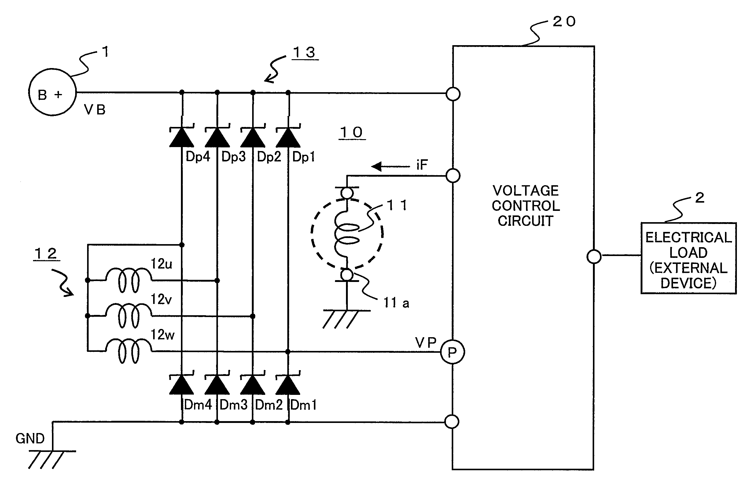
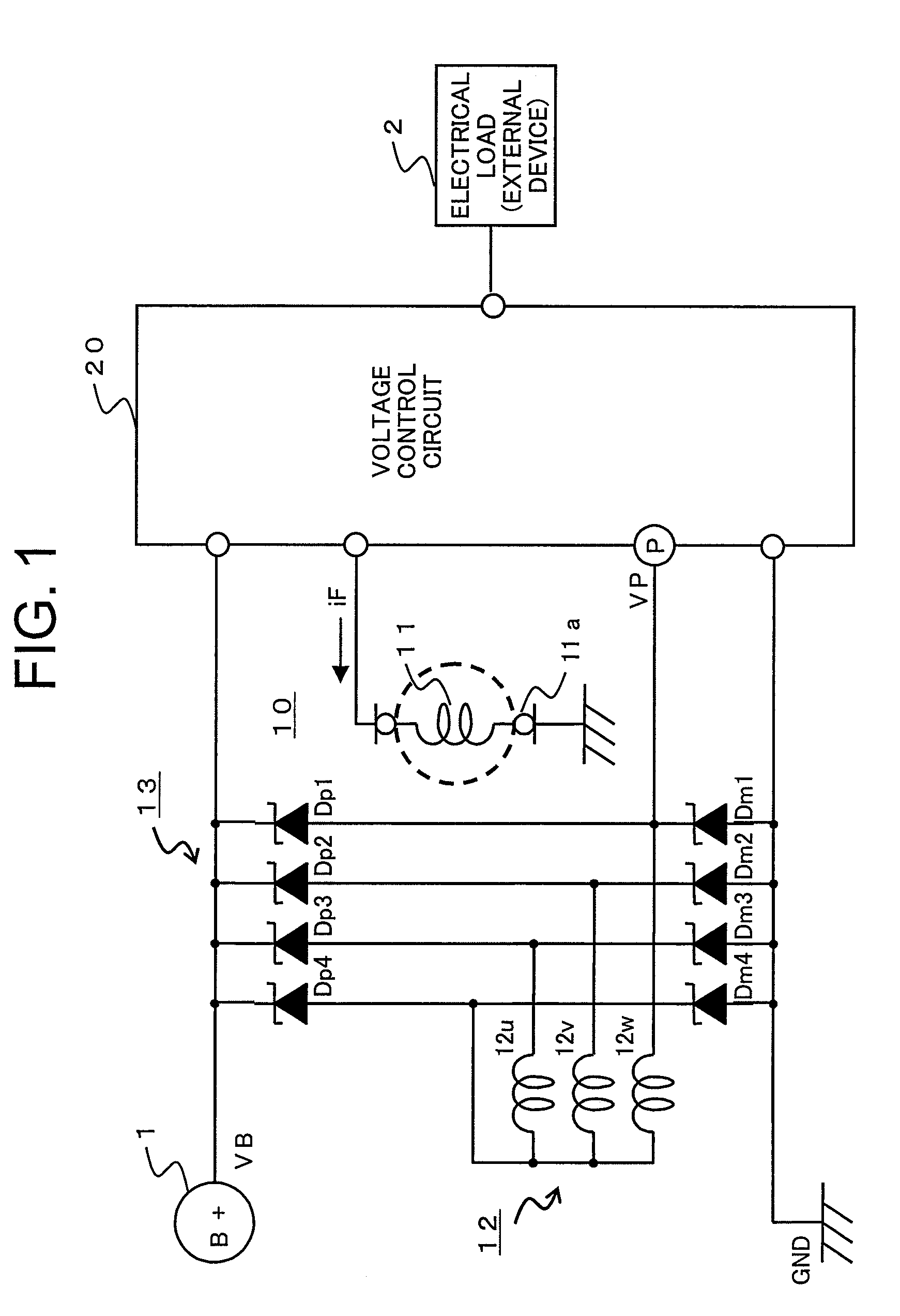
[0029]Referring to the drawings and first to FIG. 1, there is schematically shown, in a block diagram, a failure detection apparatus for an alternator according to a first embodiment of the present invention, including a power generation system and its peripheral equipment.

[0030]In FIG. 1, an on-board battery 1, which is adapted to be installed on a vehicle, generates a battery voltage VB from its positive terminal.

[0031]An alternator (alternator) 10 connected to the battery 1 includes a field coil 11 that is mounted on a rotor through a brush 11a, a three-phase armature coil 12 that is mounted on a stator in a manner to be in opposition to the field coil 11, and a full-wave rectifier circuit 13 that is electrically connected to the armature coil 12.

[0032]The full-wave rectifier circuit 13 has plus (positive) side diodes Dp (Dp1 through Dp4) and minus (negative) side diodes Dm (Dm1 through Dm4). Each of the positive side diodes Dp has a plus (positive) terminal electrically connecte...

embodiment 2

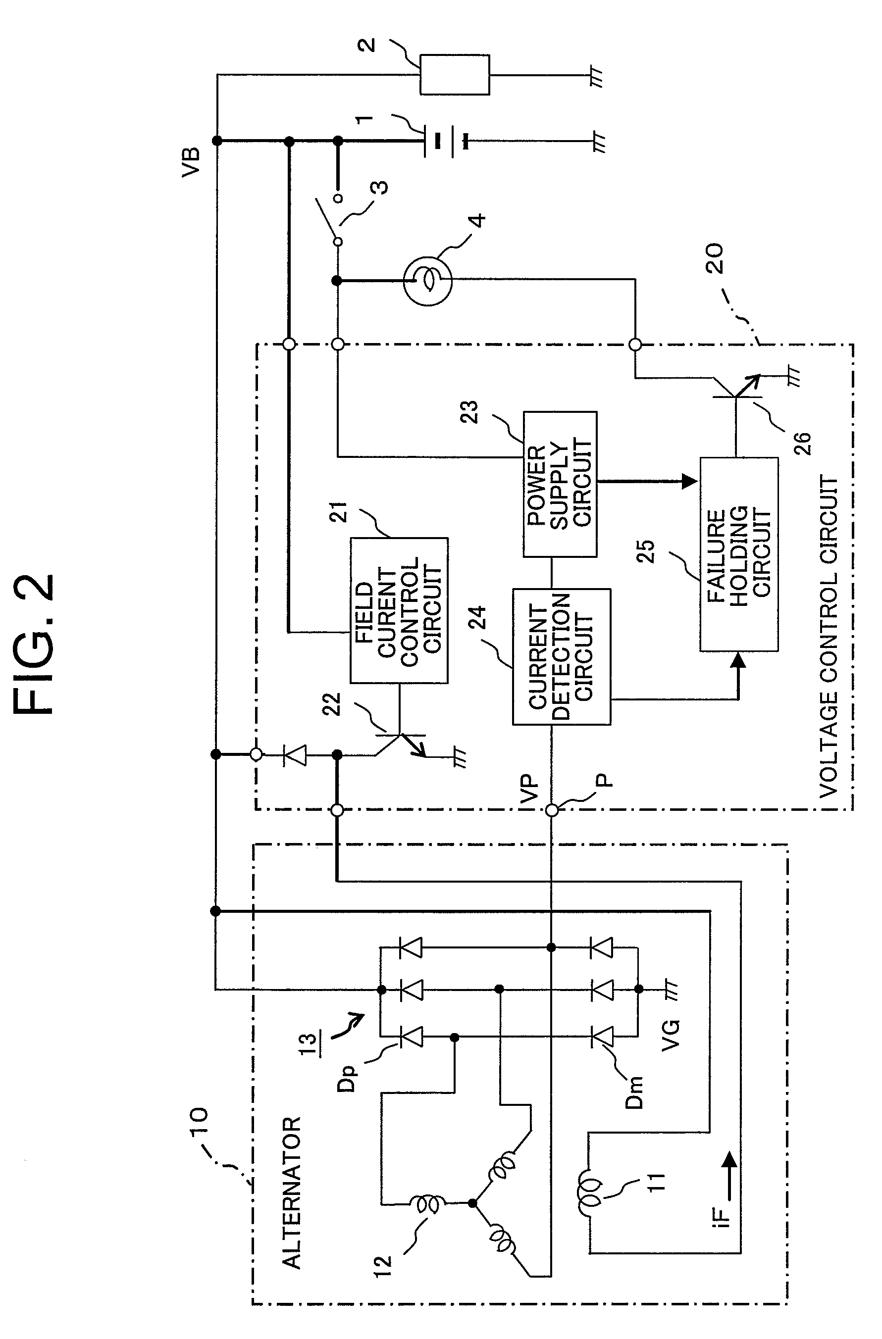
[0069]Although in the above-mentioned first embodiment (FIG. 2), the power supply circuit 23 is provided in the failure detection circuit for outputting the predetermined voltage (battery voltage VB≧predetermined voltage≧ground voltage VG), provision may be made for a drive switching circuit 27 that turns on transistors T1, T2 in a complementary manner to output the battery voltage VB or the ground voltage VG as the predetermined voltage by switching between them, as shown in FIG. 3.

[0070]FIG. 3 is a functional block diagram that shows a failure detection apparatus for an alternator according to a second embodiment of the present invention, wherein the same parts or elements as those described above (see FIG. 2) are identified by the same symbols or by the same symbols with “A” affixed to their ends, while omitting a detailed explanation thereof.

[0071]In FIG. 3, a failure detection circuit in a voltage control circuit 20A is provided, in place of the above-mentioned power supply cir...

embodiment 3

[0090]Although no reference is made to a specific determination function of the failure detection circuit (including the power supply unit and the failure holding circuit 25) in the above-mentioned first and second embodiments (FIG. 2 and FIG. 3), the power supply unit and the failure determination unit (the failure holding circuit 25) of the failure detection circuit may be constructed in a manner as shown in FIG. 4.

[0091]FIG. 4 is a functional block diagram that shows a failure detection circuit 30A according to a third embodiment of the present invention, wherein the functional configuration of a power supply unit and a failure determination unit (failure holding circuit 25) in the case of intending to perform failure detection of positive side diodes Dp of a full-wave rectifier circuit 13 is schematically illustrated. In FIG. 4, the same or like parts or elements as those described above (see FIGS. 1 through FIG. 3) are identified by the same symbols while omitting a detailed de...


PUM


Abstract

A failure detection apparatus for an alternator can detect a short circuit failure of a diode in a full-wave rectifier with high precision by use of a simple circuit structure based on the state of a detection terminal when the alternator generates no electricity. The rectifier circuit has a pair of diodes connected to a positive terminal and a negative terminal, respectively, of a battery. A failure detection circuit has the detection terminal connected to a P terminal or a neutral point of an armature coil, and makes a failure determination in the following manner. When in the non-power generation state of the armature coil, the detection terminal is in a floating or high impedance state, the full-wave rectifier circuit is determined to be normal, whereas when otherwise, the full-wave rectifier circuit is determined to be in a failure.

Description

BACKGROUND OF THE INVENTION[0001]1. Field of the Invention[0002]The present invention relates to a failure detection apparatus for an alternator (three-phase alternator), for example, mounted on a vehicle. In particular, it relates to a technique for diagnosing a short circuit failure of a rectifier diode group (hereinafter also referred to simply as “diodes”) in a full-wave rectifier circuit in an alternator.[0003]2. Description of the Related Art[0004]A known failure detection apparatus for an alternator detects a voltage duty of a phase voltage detection terminal (hereinafter referred to as a “P terminal”) during the generation of electricity, and when the voltage duty thus detected is in the vicinity of 50%, it is determined that the alternator is normal, whereas when the voltage duty deviates from 50%, it is determined that the alternator is abnormal (see, for example, a first patent document: Japanese patent application laid-open No. H8-65914).[0005]In such a known failure det...

Claims


Application Information

Patent Timeline
IPC IPC(8): F02B63/04
CPCH02P29/021G01R31/343G01R31/42H02P29/0241
Inventor NISHIMURA, SHINJISUMIMOTO, KATSUYUKI
Owner MITSUBISHI ELECTRIC CORP
Why Eureka
Try Eureka