Method and apparatus for improved current mode control for large conversion ratio synchronous buck converter with lossless current sense

a technology of lossless current sense and synchronous buck converter, which is applied in the direction of electric variable regulation, process and machine control, instruments, etc., can solve the problems of reducing the efficiency of synchronous buck converter, pulse skipping or abnormal switching, and increasing output voltage ripple, so as to improve the signal-to-noise ratio of current sense signal and improve the monitoring of output current

Inactive Publication Date: 2009-03-24
SEMTECH CORP
View PDF6 Cites 40 Cited by
  • Summary
  • Abstract
  • Description
  • Claims
  • Application Information

AI Technical Summary

Benefits of technology

[0015]The present invention overcomes the shortcomings of the prior art by providing a method and apparatus for improving the signal-to-noise ratio of a current sense signal generated by the current sensor circuitry of a power converter, such as a synchronous buck converter or the like.
[0016]In accordance with one aspect of the embodiments described herein, there is provided a DC-to-DC power converter with improved monitoring of output inductor current to a load, comprising: at least one power switch connected to an input voltage source; an output inductor connected to the at least one power switch and to the load; and a current sensor circuitry coupled to the output inductor, the current sensor circuitry providing a current sense signal corresponding to current passing through an internal DC resistance of the output inductor. The current sensor circuitry includes: a filter comprising a first resistor connected in series with a first capacitor; and a second capacitor connected in parallel with the first resistor, wherein the first and second capacitors form an AC voltage divider. The second capacitor is preferably characterized by a second capacitance value that is at least one order of magnitude smaller than a first capacitance value of the first capacitor, resulting in an increased signal-to-noise ratio for the current sense signal.
[0019]In accordance with yet another aspect of the embodiments described herein, there is provided a method for monitoring output current in a DC-to-DC power converter, wherein the power converter comprises at least one power switch, an output inductor operatively coupled to the at least one power switch, and a current sensor operatively coupled to the output inductor. The method generally comprises measuring the output current passing through the output inductor using the current sensor, wherein the current sensor includes: a filter comprising a first resistor coupled in series and a first capacitor; and a second capacitor coupled in parallel with the first resistor, the first and second capacitors forming an AC voltage divider. The method further comprises generating a current sense signal corresponding to the output current, wherein the AC voltage divider increases signal-to-noise ratio of the current sense signal for improved monitoring of the output current.

Problems solved by technology

A significant drawback of this approach is that the sensing resistor wastes the output energy and thereby reduces the efficiency of the synchronous buck converter.
As the duty ratio D approaches 0 or 1, the sensed voltage ripple can get very small and easily lead to pulse skipping or abnormal switching.
The consequences of this include (1) increased output voltage ripple, (2) degraded EMI condition, (3) reduced circuit stability region, and (4) over stress of the power circuitry components.

Method used


Image

  • Method and apparatus for improved current mode control for large conversion ratio synchronous buck converter with lossless current sense
  • Method and apparatus for improved current mode control for large conversion ratio synchronous buck converter with lossless current sense
  • Method and apparatus for improved current mode control for large conversion ratio synchronous buck converter with lossless current sense

Examples


Embodiment Construction

[0032]The present invention satisfies the need for in improved way to sense the inductor output current delivered to a load by a buck-type DC-to-DC switched mode power converter, particularly when the duty ratio D approaches 0 or 1. In the detailed description that follows, like element numerals are used to describe like elements illustrated in one or more of the drawings.

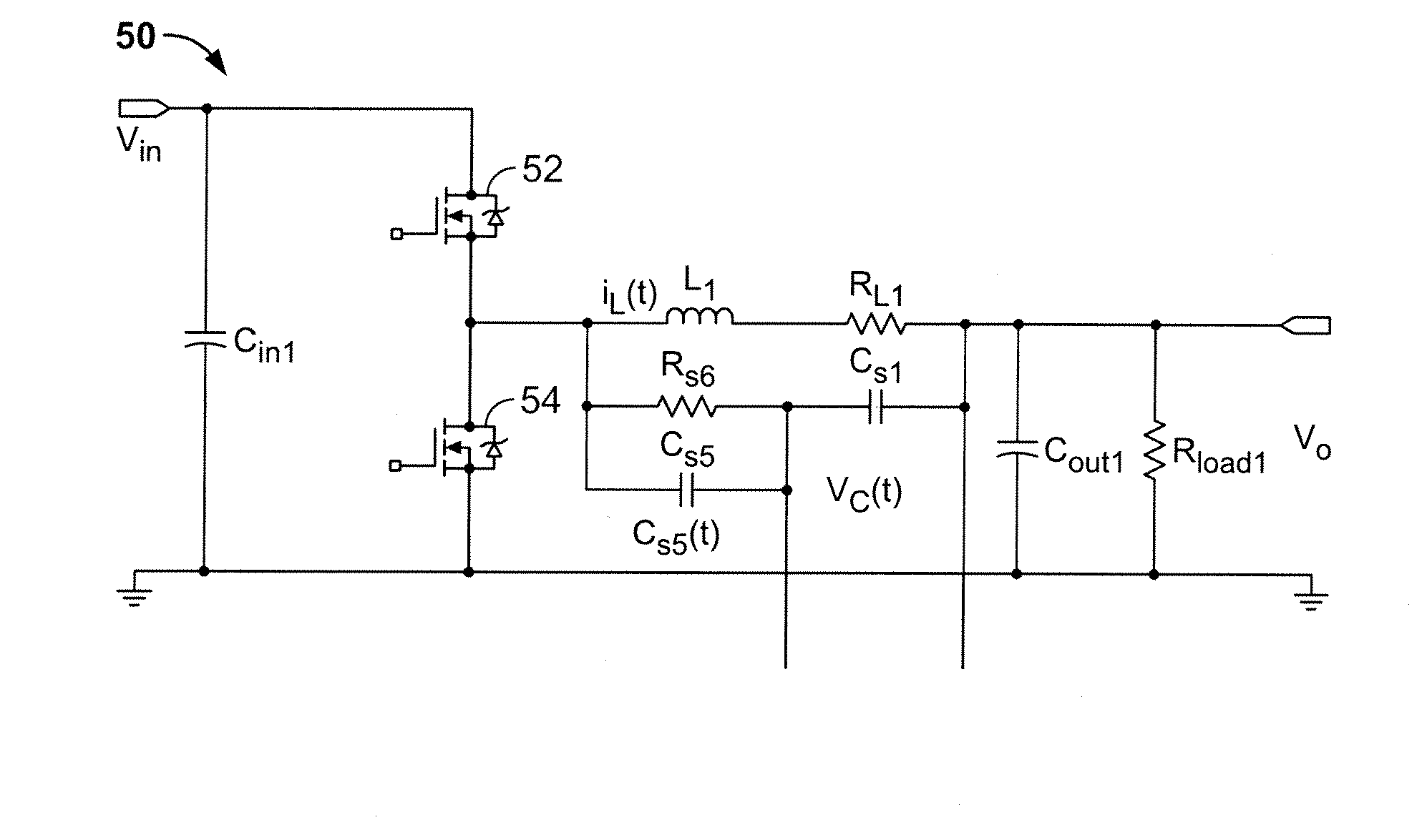
[0033]In accordance with one aspect of the embodiments described herein, there is provided a DC-to-DC power converter with improved sensed current signal-to-noise ratio (SNR) for reliable circuit operation under current mode control. With reference to FIG. 6, in one embodiment, the DC-to-DC power converter 50 provides an output voltage (Vo) to a load (Rload1), schematically represented as a resistor. The power converter further includes a high-side power switch 52 and a low-side power switch 54 connected to an input voltage source (Vin). The high-side power switch 52 and the low-side power switch 54 are generally p...


PUM


Abstract

Methods and apparatuses are provided for monitoring an inductor output current delivered to a load by a power converter. For example, there is provided an apparatus comprising: at least one power switch operatively coupled to an input voltage source; an output inductor operatively coupled to the at least one power switch and to the load; and a current sensor operatively coupled to the output inductor, the current sensor providing a current sense signal corresponding to the inductor output current delivered to the load. In one embodiment, the current sensor comprises: a filter comprising a first resistor coupled in series with a first capacitor; and a second capacitor coupled in parallel with the first resistor, the first and second capacitors forming an AC voltage divider to increase the signal-to-noise ratio of the current sense signal.

Description

RELATED APPLICATION DATA[0001]This patent application claims priority pursuant to 35 U.S.C. § 119(e) to provisional patent application Ser. No. 60 / 730,586, filed Oct. 26, 2005.BACKGROUND OF THE INVENTION[0002]1. Field of the Invention[0003]The present invention relates to switching mode power converter circuits, and more particularly, to an improved method and apparatus for monitoring the current sent to the load associated with a power converter circuit.[0004]2. Description of Related Art[0005]Switched mode DC-to-DC power converters are commonly used in the electronics industry to convert an available direct current (DC) level voltage to another DC level voltage. A switched mode converter provides a regulated DC output voltage by selectively storing energy by switching the flow of current into an output inductor coupled to a load. A synchronous buck converter is a particular type of switched mode converter that uses two power switches, such as MOSFET transistors, to control the flo...

Claims


Application Information

Patent Timeline
Patent Type & Authority Patents(United States)
IPC IPC(8): G05F1/575G05F1/618
CPCH02M3/1588H02M2001/0009Y02B70/1466Y02B70/10H02M1/0009
Inventor CHANG, CHIN
Owner SEMTECH CORP
Why Eureka
Try Eureka