
Silicon-made magnetic head slider

a slider and magnetic head technology, applied in the direction of recording head housing/shield, magnetic recording, maintaining head carrier alignment, etc., can solve the problems of reducing reliability, affecting the flight height of the slider, and the inability to record magnetic data, etc., to achieve the effect of improving the productivity of the slider, reducing the cost, and improving the flying heigh

Inactive Publication Date: 2009-03-24
HITACHI GLOBAL STORAGE TECH NETHERLANDS BV
View PDF10 Cites 2 Cited by
  • Summary
  • Abstract
  • Description
  • Claims
  • Application Information

AI Technical Summary

Benefits of technology

"The invention provides a magnetic disk device and a magnetic head slider that can improve productivity and cost reduction while ensuring reliability. The magnetic head slider has a silicon slider-substrate-portion and a thin-film head portion formed using the thin film process. The thin-film head portion has a recording / reproduction element facing the surface of the magnetic disk and a ceramic insulation film made of alumina and silicon-based ceramics. The ceramic insulation film has a similar coefficient of linear expansion to the silicon slider substrate portion, reducing thermal irregularity and improving recording / reproduction performance. The invention also provides a more preferable configuration for the ceramic insulation film."

Problems solved by technology

It was found that when the material of the slider substrate portion was merely substituted for the silicon material in the conventional magnetic-head-slider comprising the slider substrate portion formed using AlTiC and the thin-film head portion having the alumina insulation film, although an advantage of low process cost was provided, thermal irregularity was produced in the thin-film head portion due to change of ambient temperature, resulting in a decrease in reliability.
When the magnetic head slider contacts the magnetic disk, the magnetic data cannot be recorded / reproduced due to the effect of frictional vibration, or the recording / reproduction element may be damaged due to abrasion.
To prevent the contact even at high temperature, designed flying height or the distance between the recording / reproduction element and the magnetic disk must be sufficiently large, resulting in the difficulty in improving recording / reproduction performance.
In addition, the thin-film head portion is retracted from the air-bearing surface at low temperature, and the distance between the read / write element and the magnetic disk becomes too large compared with the designed value, resulting in a reduction in read / write performance.
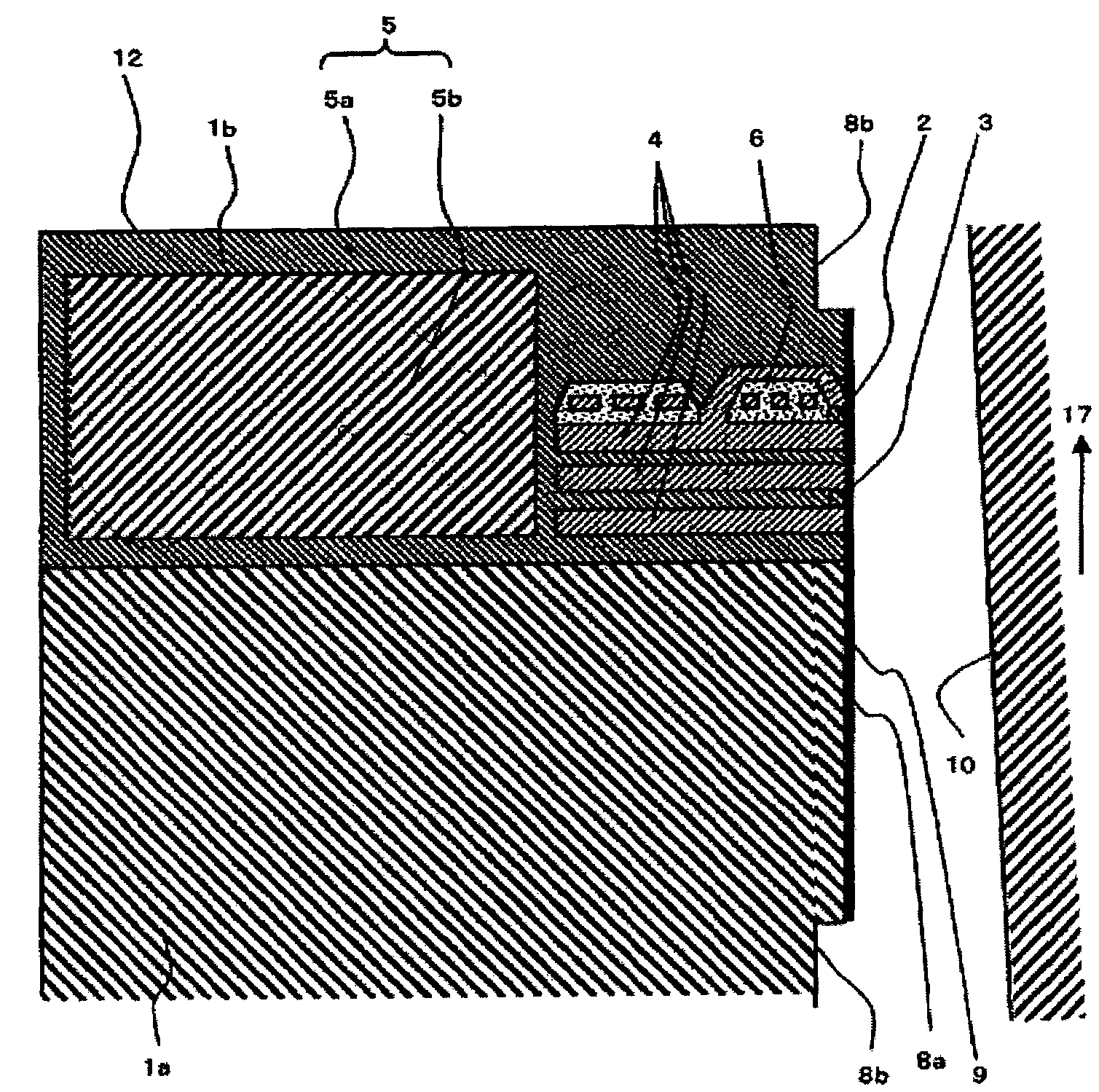
Contrarily, when the coefficient of linear expansion of the thin-film head portion is small compared with the slider substrate portion, a convex portion is produced in the air-bearing surface at low temperature, resulting in an increase in the risk of the contact of the magnetic head slider with the magnetic disk.
In addition, a concave portion is produced at high temperature, resulting in an excessively large distance between the recording / reproduction element and the magnetic disk compared with the designed value.
However, in the magnetic head slider of the patent literature 1, the coefficient of linear expansion of silicon, which is the material of the slider substrate, is about 3 ppm / K, and when alumina is used for the ceramic insulation film of the thin-film head, the coefficient of linear expansion of alumina is too large compared with that of the slider substrate, because it is about 7 ppm / K.

Method used


Image

  • Silicon-made magnetic head slider
  • Silicon-made magnetic head slider
  • Silicon-made magnetic head slider

Examples


first embodiment

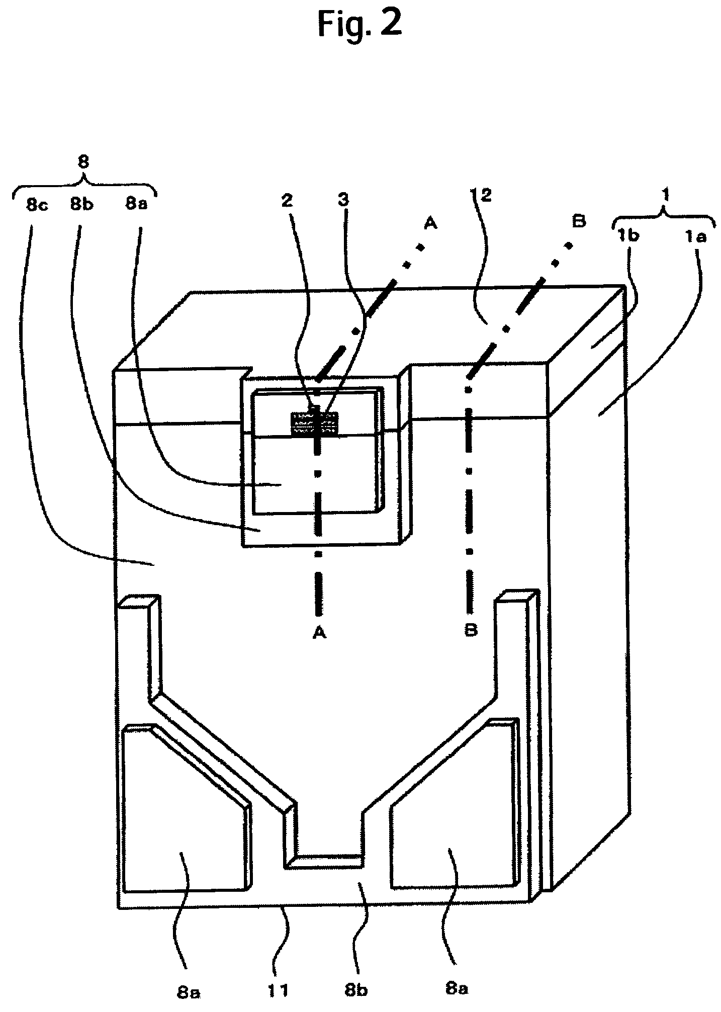
[0037]Hereinafter, several embodiments of the invention are described using drawings. Same references in figures in respective embodiments indicate same or corresponding articles. First, a magnetic disk device and a magnetic head slider of the invention are described using FIG. 1 to FIG. 7.

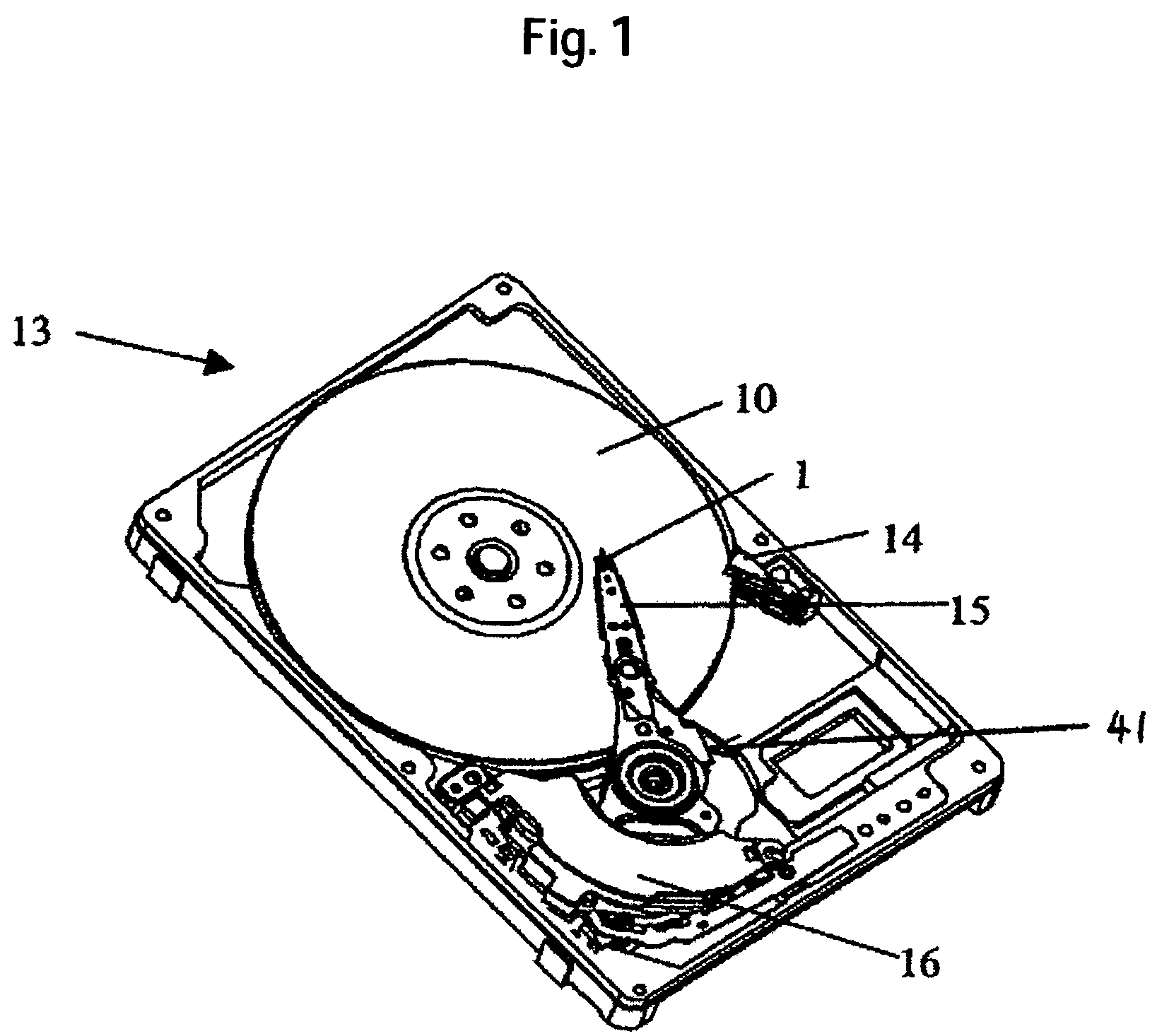
[0038]A general configuration of the magnetic disk device according to the first embodiment is described with reference to FIG. 1. FIG. 1 is a perspective view of the magnetic disk device of the first embodiment of the invention.

[0039]A magnetic disk device 13, which is used for a hard disk device mounted in a computer unit, is configured to have a magnetic disk 10 arranged rotatably, a magnetic head slider 1 arranged in a way of facing a surface of the magnetic disk, and a driving unit 41 for moving the magnetic head slider 1 in a radial direction of the surface of the magnetic disk 10. The magnetic disk device 13 is configured in a way of generating an air stream between the magnetic disk 10 tha...

third embodiment

[0071]In the third embodiment, the alumina thin-film portion 5a and the silica thin-film portion 5b are used properly in a layer direction along which thin films forming the thin-film head portion 1b are sequentially formed. In the magnetic head slider 1 shown in FIG. 9, the alumina thin-film portion 5a is formed on both sides of the silica thin-film portion 5b. The silica thin-film portion 5b is formed on a layer including the metal film 4 and the recording / reproduction elements 2, 3. In the magnetic head slider 1 shown in FIG. 10, the silica thin-film portion 5b is formed in the same layers as top and bottom shields of the reproduction element 3, in the same layer as a lower magnetic-pole of the recording element 2, and formed above an upper magnetic pole of the element 2, respectively.

[0072]Again in the thin-film head structure of the third embodiment, the effect of reducing the thermal irregularity due to a change of ambient temperature can be obtained. Again in this case, it is...


PUM

PropertyMeasurementUnit
flying heightaaaaaaaaaa
thickaaaaaaaaaa
thickaaaaaaaaaa

Abstract

In a magnetic disk device, cost reduction is designed by improving productivity, and increase in recording density and increase in capacity of the device or size reduction are designed with reliability being ensured. In one embodiment, a magnetic disk device has a magnetic disk arranged rotatably, a magnetic head slider arranged in a manner of facing a surface of the magnetic disk, and a driving device for moving the magnetic head slider in a radial direction of the surface of the magnetic disk. The magnetic head slider has a silicon slider-substrate-portion and a thin-film head portion which is formed on the slider substrate portion using a thin-film process and forms an air-bearing surface along with the slider substrate portion. The thin-film head portion has recording / reproduction elements facing the surface of the magnetic disk, and a ceramic insulation film has alumina and silicon-based ceramics in order to have a coefficient of linear expansion approximately equal to that of the silicon slider-substrate-portion.

Description

CROSS-REFERENCES TO RELATED APPLICATIONS[0001]This application claims priority from Japanese Patent Application No. JP2004-287446, filed Sep. 30, 2004, the entire disclosure of which is incorporated herein by reference.BACKGROUND OF THE INVENTION[0002]The present invention relates to a magnetic disk device and a magnetic head slider and, more particularly, to a magnetic head slider having a thin-film head portion formed on a slider substrate portion using a thin-film process and a magnetic disk device using the slider.[0003]In the magnetic disk device, a magnetic head slider mounted with a recording / reproduction element flies from a magnetic disk due to a wedge film effect of air, so that recording / reproduction of magnetic data on the magnetic disk is performed. To realize high recording density of the magnetic disk device and resultant increase in capacity of the device or size reduction, it is effective that distance between the magnetic head slider and the magnetic disk (flying h...

Claims


Application Information

Patent Timeline
Patent Type & Authority Patents(United States)
IPC IPC(8): G11B15/64
CPCG11B5/10G11B5/3133G11B5/3136G11B5/6005G11B5/3106G11B5/6082
Inventor ETOH, KIMITOSHIKURITA, MASAYUKIMIKIO, TOKUYAMATOSHIYA, SHIRAMATSU
Owner HITACHI GLOBAL STORAGE TECH NETHERLANDS BV
Learn More