Method and apparatus for channel estimation in radio systems by MMSE-based recursive filtering

a radio system and channel estimation technology, applied in the field of method and apparatus for calculation of filtered channel estimation value in radio system, can solve the problems of inconvenient use of iir filters, inability to correct detection of transmitted data, etc., and achieve the effect of reducing resource consumption

Inactive Publication Date: 2009-03-24
INTEL CORP
View PDF18 Cites 6 Cited by
  • Summary
  • Abstract
  • Description
  • Claims
  • Application Information

AI Technical Summary

Benefits of technology

[0012]The invention is based on the object of providing a filter unit for a channel estimator, which can cope with all the scenarios which occur (different SINR, different relative speeds between the transmitter and the receiver) with as

Problems solved by technology

The signal distortion which is caused by the multipath propagation makes correct detection of the transmitted data impossible without a correction mec

Method used


Image

  • Method and apparatus for channel estimation in radio systems by MMSE-based recursive filtering
  • Method and apparatus for channel estimation in radio systems by MMSE-based recursive filtering
  • Method and apparatus for channel estimation in radio systems by MMSE-based recursive filtering

Examples


Embodiment Construction

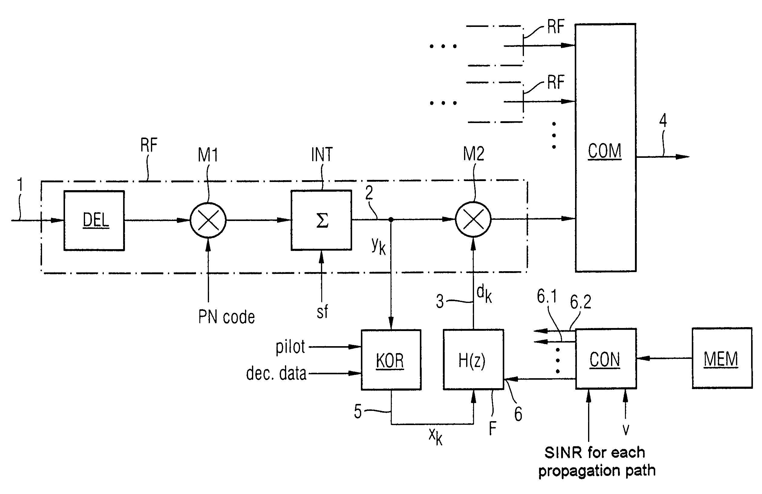
[0042]As is shown in FIG. 1, a conventionally designed Rake receiver has two or more Rake fingers RF, whose outputs are supplied to a combiner COM. A digital signal 1 is supplied to the input side of the Rake fingers RF, of which only one is illustrated in detail by way of example in FIG. 1, with this digital signal 1 normally having been produced in the conventional manner (not illustrated) by down-mixing an antenna signal to an intermediate frequency band or to baseband and by sampling the down-mixed signal using a sufficiently high sampling frequency. The digital signal 1 is supplied to a delay element DEL whose object is to compensate for the path delay measured for a specific propagation path. A multiplier M1 is connected downstream from the delay element DEL in the signal path, in order to despread the delay-compensated digital signal. The signal which is emitted from the delay stage DEL is multiplied by a spreading code PN (pseudo noise) for this purpose.

[0043]An integrate an...


PUM


Abstract

A sequence of unfiltered channel estimation values xk is determined in a method for calculation of filtered channel estimation values dk in radio systems. A specific set of filter coefficients is selected from two or more filter coefficient sets, with the filter coefficients being calculated on the basis of the MMSE optimality criterion for a predetermined recursive digital filter (F). The sequence of unfiltered channel estimation values is then filtered by means of this recursive digital filter (F) using the selected filter coefficients.

Description

PRIORITY[0001]This application claims priority to German application no. 103 16 803.6 filed Apr. 11, 2003.TECHNICAL FIELD OF THE INVENTION[0002]The invention relates to a method and an apparatus for calculation of filtered channel estimation values in radio systems, in particular in mobile radio systems.BACKGROUND OF THE INVENTION[0003]In mobile radio systems, the signals are propagated via a number of propagation paths between the transmitter and the receiver. The influence of this multipath propagation on the signal may be described in the form of a linear, time-variant transformation. The signal distortion which is caused by the multipath propagation makes correct detection of the transmitted data impossible without a correction mechanism. This correction mechanism, which is referred to as adaptive equalization, is based on continuously repeated measurement of the channel characteristics of the transmission channel (channel estimation). The information which is determined about t...

Claims


Application Information

Patent Timeline
IPC IPC(8): H03H7/30H04B1/707H04L25/02
CPCH04L25/0234
Inventor DENK, ROBERT
Owner INTEL CORP
Why Eureka
Try Eureka