
HVAC communication system

a communication system and hvac technology, applied in the field of single-wire interface communication systems, can solve the problems of inability of temperature sensors and mercury switches to accommodate digital communication, energy continues to rise, and complicated heating and cooling of homes

Inactive Publication Date: 2009-03-31
EMERSON ELECTRIC CO
View PDF12 Cites 212 Cited by
  • Summary
  • Abstract
  • Description
  • Claims
  • Application Information

AI Technical Summary

Problems solved by technology

As the cost of energy continues to rise, heating and cooling a home has become a complicated activity.
This need for a communication link to the interior of a consumer's home presents two problems: first, traditional thermostats that use bimetal temperature sensors and mercury switches are incapable of accommodating digital communication.
Second, a traditional heating, ventilation and air conditioning (HVAC) system includes only a few control wires.
As such, even where a mechanical thermostat is replaced with an electronic one having a microprocessor capable of communicating with other devices, there is no suitable communication bus with which to connect an exterior data device with the thermostat.
This solution, however, is both time consuming and expensive.
Often this installation can be cost prohibitive for consumers.
The problem with this solution is that such a wireless connection requires more power than can be sourced by the 24-volt wire running to the thermostat.
Again, installation of additional wiring into existing structures may be cost prohibitive.
While a battery may be used to power the wireless communication system, the user must take care to ensure that the batteries are continually replaced, which is inconvenient and costly.
Further complicating matters, reception problems may exist with wireless systems due to interior walls and signal multipaths.

Method used


Image

  • HVAC communication system
  • HVAC communication system
  • HVAC communication system

Examples


Embodiment Construction

[0018]Before describing in detail embodiments that are in accordance with the present invention, it should be observed that the embodiments reside primarily in combinations of method steps and apparatus components related to a communication system capable of operating with traditional HVAC wiring. The apparatus components and method steps have been represented where appropriate by conventional symbols in the drawings, showing only those specific details that are pertinent to understanding the embodiments of the present invention so as not to obscure the disclosure with details that will be readily apparent to those of ordinary skill in the art having the benefit of the description herein.

[0019]It will be appreciated that embodiments of the invention described herein may be comprised of one or more conventional processors and unique stored program instructions that control the one or more processors to implement, in conjunction with certain non-processor circuits, some, most, or all ...


PUM


Abstract

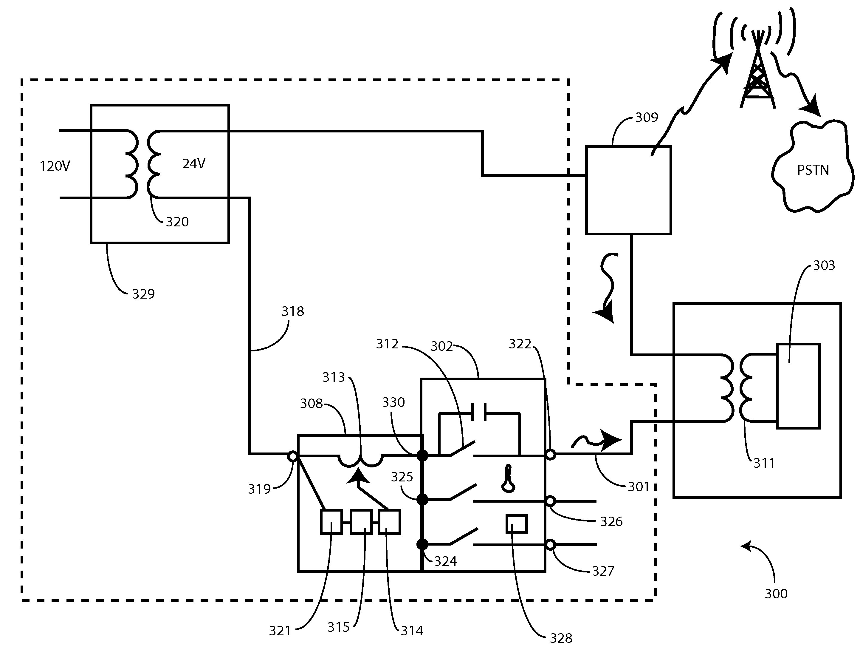
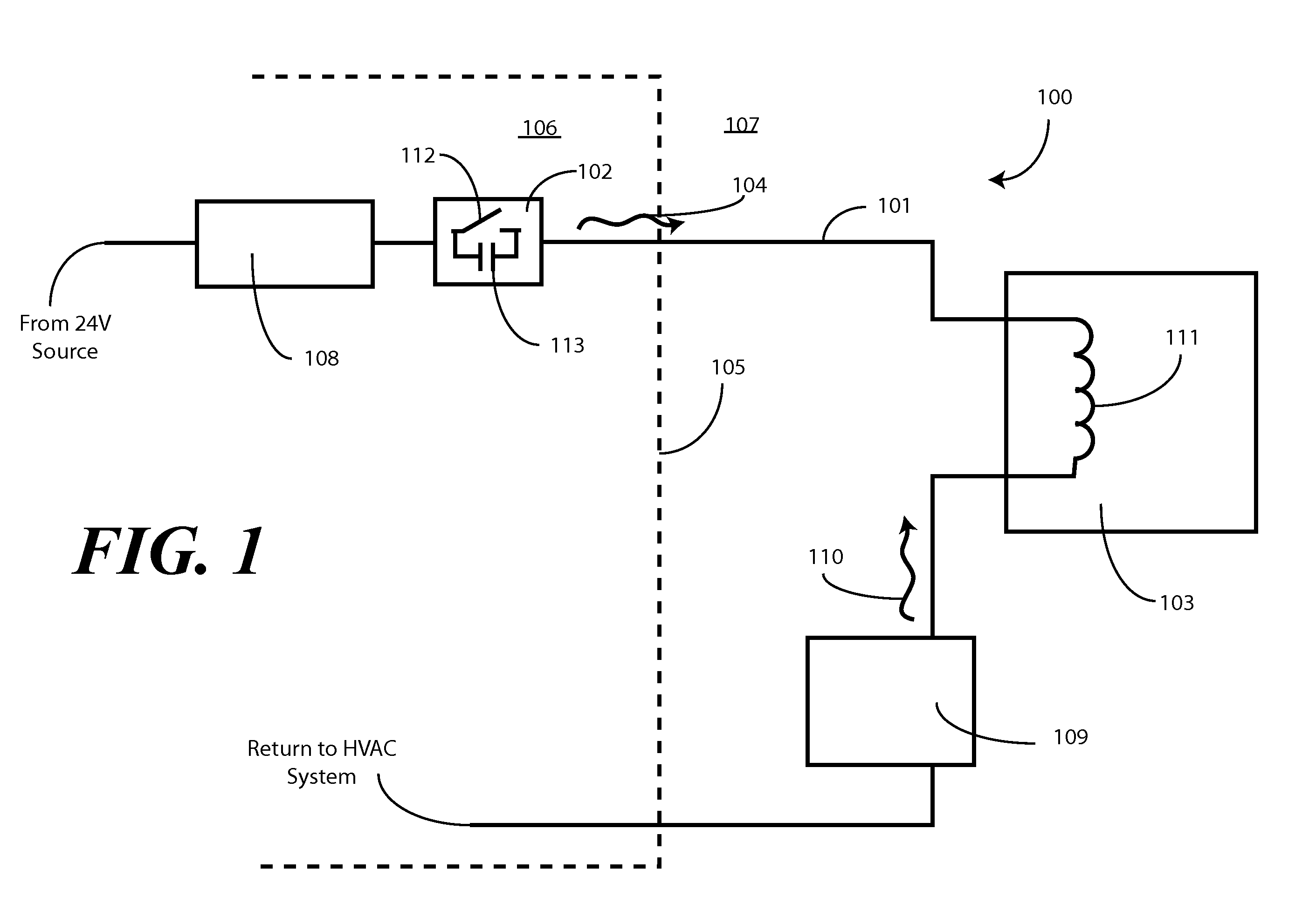
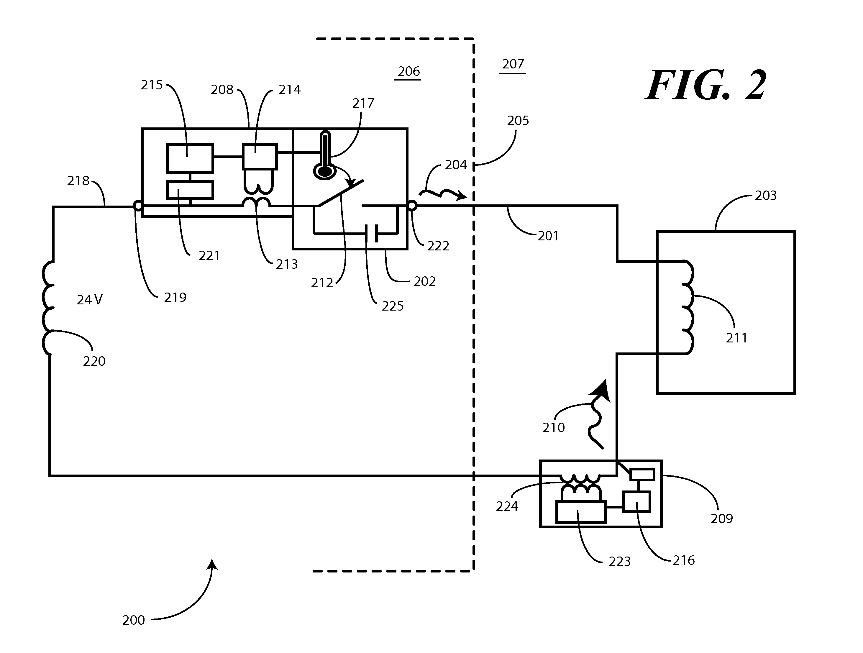
A system for communicating across conventional HVAC wiring is provided. The system includes a communication device having a communication module capable of inducing low power, high frequency current signals into a single control wire coupling, for example, a thermostat with a compressor. The communication module includes a power supply module that draws power sufficient to operate the communication module from the existing HVAC wiring, so as to eliminate any need for batteries or external power sources. A second communication module may be coupled to the single control wire. The second communication module operates as a transceiver sending communication signals to, and receiving communication signals from, the communication module. In one embodiment, the communication module is disposed within a building, for example coupled to an electronic thermostat, while the second communication module is disposed outside the building near the compressor. The communication signals are RF modulated signals between 5 and 50 MHz so as to take advantage of and pass across parasitic capacitances found inherent in transformers or other coils disposed within HVAC loads.

Description

CROSS REFERENCE TO PRIOR APPLICATIONS[0001]This application is a divisional application claiming priority from U.S. application Ser. No. 11 / 301,447, filed Dec. 13, 2005, now U.S. Pat. No. 7,163,158 entitled “HVAC Communication System.”BACKGROUND[0002]1. Technical Field[0003]This invention relates generally to a communication system for a single-wire interface, and more particularly to a communication system capable of communicating between, for example, a thermostat and a receiving unit disposed near or in an air compressor by way of high frequency current modulation along a single HVAC control wire.[0004]2. Background Art[0005]As the cost of energy continues to rise, heating and cooling a home has become a complicated activity. When natural gas, heating oil and electric power were plentiful and inexpensive, one may simply have set the thermostat on 78 in the summer and 68 in the winter to adequately heat and cool a house. Under such a plan, they may only touch the thermostat twice ...

Claims


Application Information

Patent Timeline
Patent Type & Authority Patents(United States)
IPC IPC(8): G05D23/00G05B11/01G08B1/08H04M11/04F24F11/76
CPCF24F11/0009F24F2011/0068F24F11/30F24F11/56F24F11/88F24F11/47F24F11/33F24F11/63
Inventor ROSSI, JOHN F.HUDDLESTON, PAUL MICHAELBARTON, MARK LEESMITH, BRADLEY A.NG, HOWARDMUELLER, CARL J.GAROZZO, JAMES P.BARRETT, CECIL H.HOUSE, RUSSELL THOMAS
Owner EMERSON ELECTRIC CO
Learn More