Encryption for optical communications using dynamic subcarrier multiplexing

a technology of optical communication and subcarrier multiplexing, applied in the direction of logic circuits, pulse techniques, instruments, etc., can solve the problems of increasing the complexity of the system, affecting the optimal use of the communication link, and the conversion and data encryption steps introduce a severe bottleneck in the optical communication path

Inactive Publication Date: 2009-03-31
LOCKHEED MARTIN CORP
View PDF23 Cites 11 Cited by
  • Summary
  • Abstract
  • Description
  • Claims
  • Application Information

AI Technical Summary

Benefits of technology

[0005]The instant invention is a multiplexing technique for optical communications used to create a pseudo-random communications signal in the optical domain such that only the sender and / or receiver can decode the signal. The multiplexing technique may include one or more information-bearing optical signals combined with one or more dynamic pseudo-randomly-generated optical signals to create a combined, dynamic subcarrier multiplexed privacy-protected output signal. The information-bearing signal is protocol-independent and can be of mixed type, such as RF, analog, or digital. The receiver of the privacy-protected signal may decode the pseudo-random signal so as to disclose the information-bearing signal. One of the unique characteristics of the present invention is the use of dynamic subcarrier multiplexing selection based on standard digital encryption and the use of optical range time to ensure synchronization.

Problems solved by technology

These additional steps increase the complexity of the system and interfere with optimal use of the communications link.
The analog conversion and data encryption steps introduce a severe bottleneck in an optical communications path due to the limited performance of digital electronics when compared to the extremely high bandwidth of optical fiber.

Method used


Image

  • Encryption for optical communications using dynamic subcarrier multiplexing
  • Encryption for optical communications using dynamic subcarrier multiplexing
  • Encryption for optical communications using dynamic subcarrier multiplexing

Examples


Embodiment Construction

[0011]Optical data transmission systems allow information to be transmitted in the form of light. Generally, a fiber optic cable forms a conduit through which an information bearing signal can be relayed from a transmitter to a receiver. The information bearing signal may be transmitted through the air if desired as long as some sort of a receiver is in the line of sight of the transmitter. However, fiber optic cables are preferred because they can transmit light at extremely high speed with relatively small power loss beyond the line of sight.

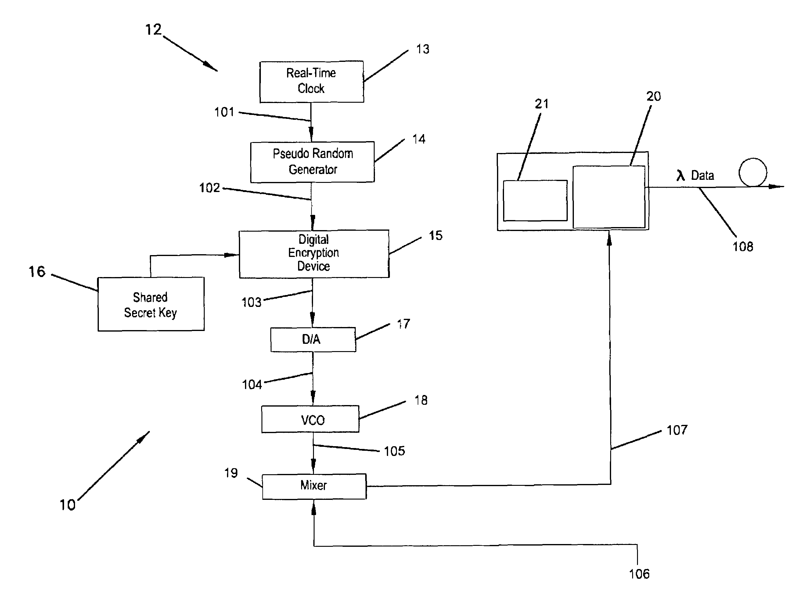
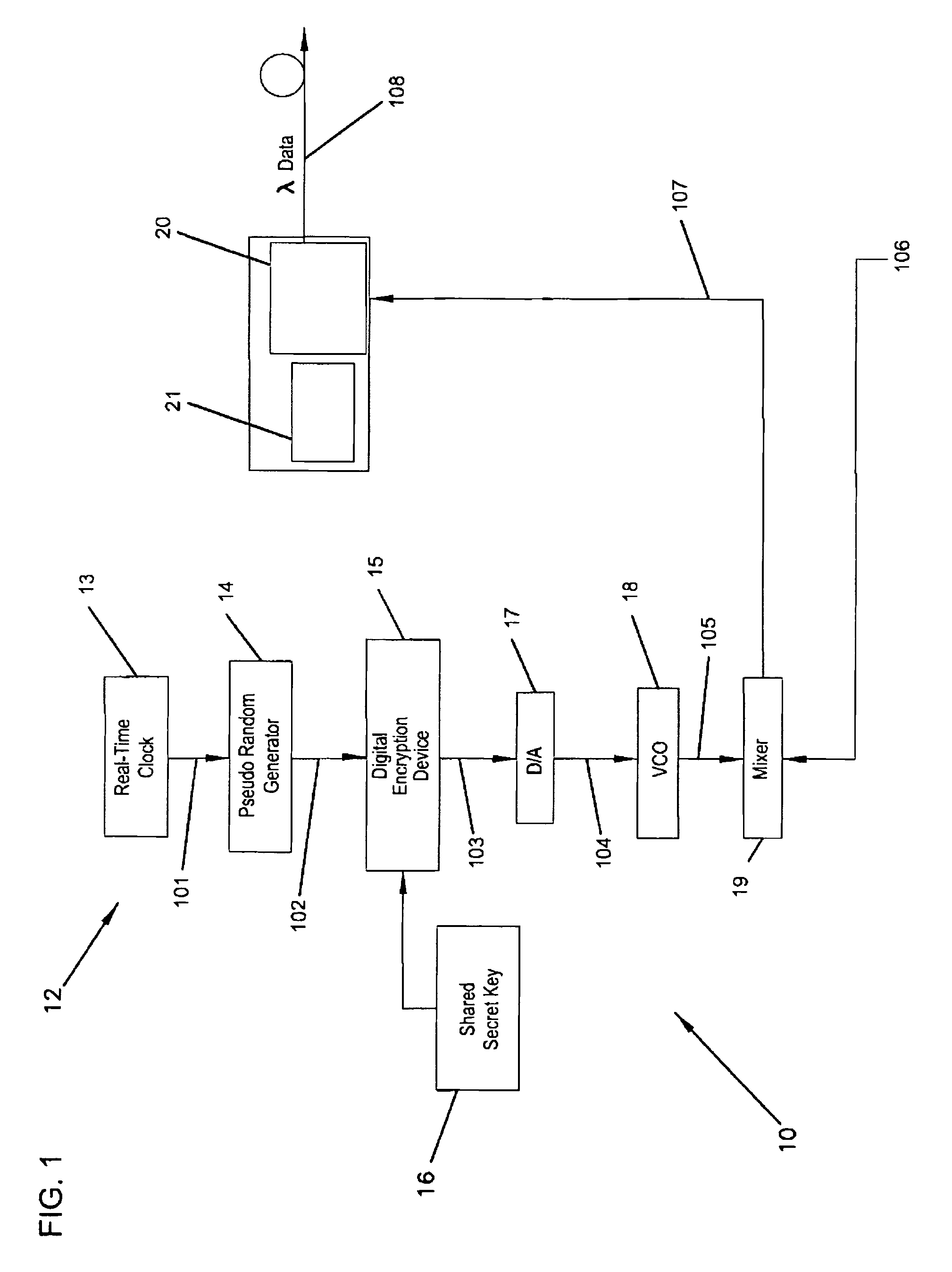
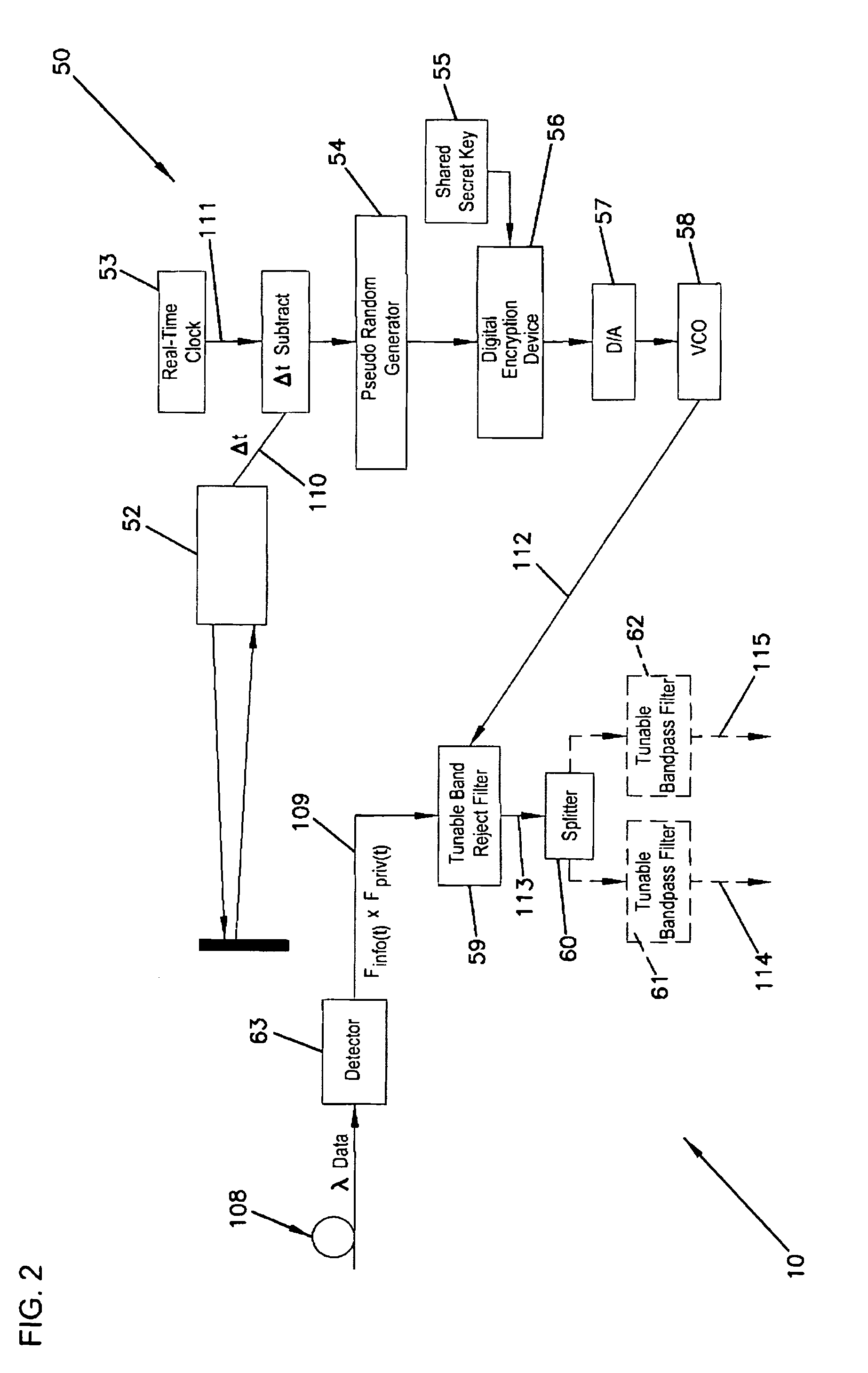
[0012]In a first embodiment, the present invention is a multiplexing method for secure communications over fiber optic cables. The method includes creating one or more information-bearing optical signals and then said information-bearing optical signals are combined with one or more dynamic pseudo-randomly-generated optical signals to create a combined, dynamic subcarrier multiplexed privacy-protected output signal. The pseudo-randomly-generat...


PUM


Abstract

A multiplexing technique for optical communications used to create a pseudo-random communications signal in the optical domain such that only the sender and/or receiver can decode the signal. The multiplexing technique may include one or more information-bearing optical signals combined with one or more dynamic pseudo-randomly-generated optical signals to create a combined dynamic subcarrier multiplexed privacy-protected output signal. The information-bearing signal is protocol-independent and can be of mixed type, such as RF, analog, and/or digital. Only the receiver of the privacy-protected signal may decode the pseudo-random signal so as to disclose the information-bearing signal. The present invention may use dynamic subcarrier multiplexing selection based on standard digital encryption and the use of optical range time to ensure synchronization.

Description

FIELD OF THE INVENTION[0001]The present invention relates generally to optical data transmission systems and more particularly to encryption techniques for secure data transmission over fiber optic networks.BACKGROUND OF THE INVENTION[0002]The current approach to protection of signals transmitted over optical communications links is to perform an analog-to-digital conversion, apply digital encryption to the digital data stream, and convert the digital data stream back to analog. For example, U.S. Pat. No. 5,864,625 (“Methods and Apparatus for Secure Optical Communications Links”) teaches a method whereby communications information is encrypted with a security key. An optical beam is then modulated with both the security key and the encrypted communications information, with different modulation schemes being used for each. The dual-modulated optical beam is then transmitted to a receiver. At the receiver, the optical beam is split into first and second optical beams. First and secon...

Claims


Application Information

Patent Timeline
Patent Type & Authority Patents(United States)
IPC IPC(8): H04K1/00
CPCH04L9/12H04L9/0838
Inventor SCHANTZ, HOWARD J.STEVENS, RICK C.ERNST, STEVEN H.
Owner LOCKHEED MARTIN CORP
Why Eureka
Try Eureka