Ozone exhaust system for image forming apparatus

a technology of image forming apparatus and exhaust system, which is applied in the direction of oxygen/ozone/oxide/hydroxide, electrographic process, instruments, etc., can solve the problems of printing defects, damage to the photoconductive layer of the photoreceptor used in the image forming apparatus, and harmful effects on human body and environment, so as to reduce the residual ozone concentration

Inactive Publication Date: 2009-03-31
SHARP KK
View PDF5 Cites 11 Cited by
  • Summary
  • Abstract
  • Description
  • Claims
  • Application Information

AI Technical Summary

Benefits of technology

[0021]In the ozone exhaust systems of an image forming apparatus described herein, the exhaust passages for exhausting ozone may include a plurality of process printing unit's side exhaust passages provided for the respective shielding members and a main exhaust passage to which the process printing unit's side exhaust passages are connected, and the process printing unit's side exhaust passages are constructed so that the air current that flows into the shielding members and the air current that flows from the process printing unit's side exhaust passages into the main exhaust passage are directed in the same direction. This arrangement makes it possible to establish smooth flow of air from the process printing unit's side exhaust passages into the main exhaust passage. As a result, it is possible to reduce the residual ozone concentrations inside the process printing units and equalize the ozone concentrations therein.
[0022]The main exhaust passage of the ozone exhaust systems disclosed herein may be laid out on one side of the process printing units that are arranged parallel to each other, along the direction of arrangement of the process printing units; the process printing unit's side exhaust passages are extended approximately perpendicularly to the main exhaust passage and arranged parallel to each other along the direction of the air current inside the main exhaust passage; and an exhaust fan is provided for the main exhaust passage, at a position on the interior side relative to the process printing unit's side exhaust passages located at both ends. This arrangement makes it possible to provide a compact configuration without enlargement of the outside dimensions of the apparatus.
[0023]In the ozone exhaust systems disclosed herein, the joint of the process printing unit's side exhaust passage with the main exhaust passage may be arranged, slanting to the downstream side with respect to the direction of the air current that flows into the shielding member, from the position perpendicular to the main exhaust passage. This arrangement makes it possible to establish smooth flow of air from the process printing unit's side exhaust duct toward the main exhaust duct.
[0024]In the ozone exhaust systems disclosed herein, the process printing unit's side exhaust passage, being constructed so that the air current that flows into the shielding member and the air current that flows from the process printing unit's side exhaust passage into the main exhaust passage are directed in the same direction, may be joined to the main exhaust passage, at an angle equal to or smaller than 90 degrees with respect to the direction of the air current flowing through the main exhaust passage. This arrangement makes it possible to establish smooth flow of air from the process printing unit's side exhaust duct toward the main exhaust duct.
[0025]In the ozone exhaust systems disclosed herein, the process printing unit's side exhaust passage, being constructed so that the air current that flows into the shielding member and the air current that flows from the process printing unit's side exhaust passage into the main exhaust passage are directed opposite, is joined to the main exhaust passage, at an angle equal to or smaller than 90 degrees with respect to the opposite direction of the air current flowing through the main exhaust passage. This arrangement makes it possible to establish smooth flow of air from the process printing unit's side exhaust duct toward the main exhaust duct.

Problems solved by technology

Ozone not only has a harmful effect on human body and environment, but also causes damage to photoconductive layers of the photoreceptors used in image forming apparatus.
For this reason, there occurs the problem that as a result of aging or depending on the usage history of the image forming apparatus, the photoreceptor become unable to be charged with a correct voltage, inducing local fluctuation in the surface potential thereof, thus causing printing defects such as “printing blur” and “poor sensitivity”.
For such a color image forming apparatus, since provision of exhaust ducts and exhaust fans for individual process printing units leads to enlargement and cost-increase of the apparatus, it is a common practice to connect a multiple number of ducts to a single exhaust fan so as to efficiently draw the generated ozone out of the machine to thereby lessen pollution inside the apparatus.
However, in the conventional technique, there has been a problem that exhaust efficiency unevenness occurs due to the positional relationship between the exhaust fan and process printing units if ozone is tried to be removed at the same time from multiple process printing units by a single exhaust fan.
Thus, a simple arrangement of ducts just considering exhaust in the ozone exhaust system of the conventional image forming apparatus, cannot solve the uneven ozone concentration distribution problem with which parts and components exposed to high-concentration ozone are adversely affected.

Method used


Image

  • Ozone exhaust system for image forming apparatus
  • Ozone exhaust system for image forming apparatus
  • Ozone exhaust system for image forming apparatus

Examples


Embodiment Construction

[0047]The best mode for carrying out the present invention will hereinafter be described with reference to the drawings.

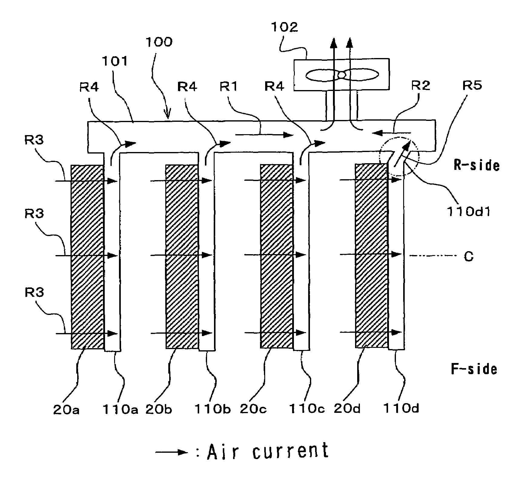
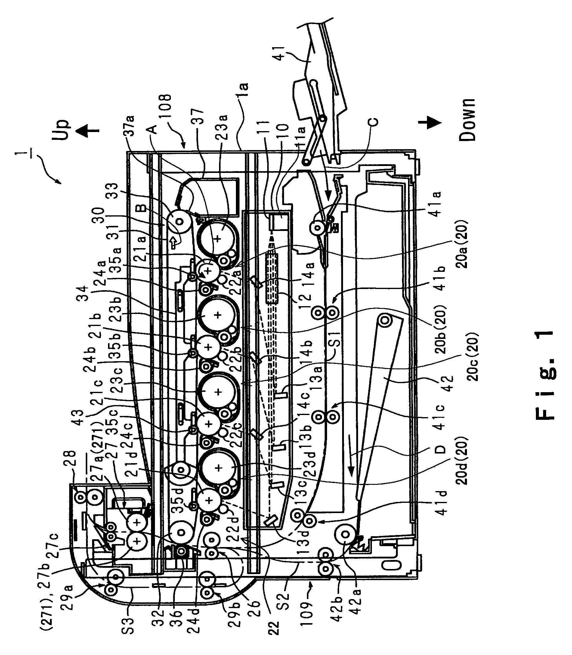
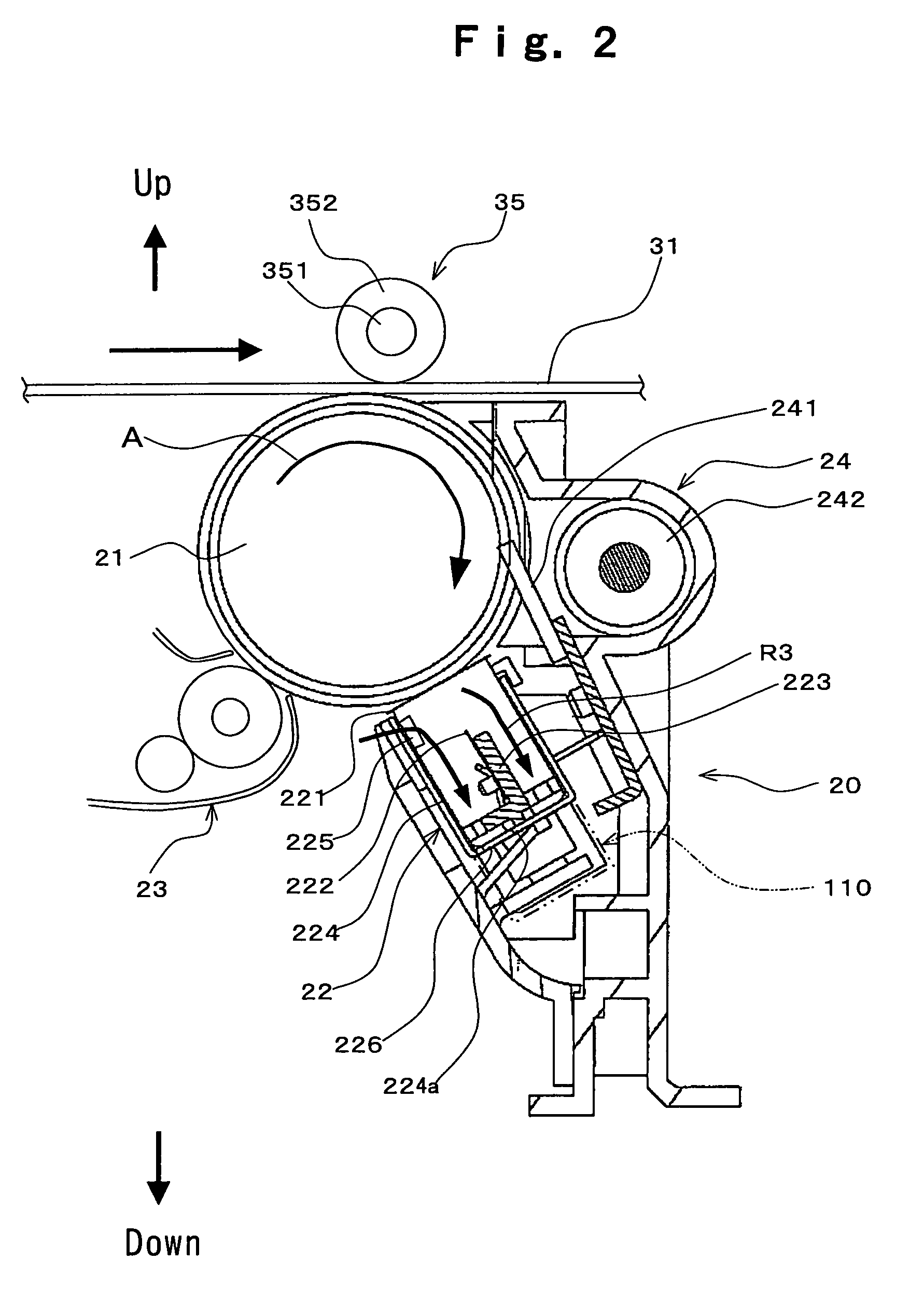
[0048]FIGS. 1 to 3 show one embodiment mode of the present invention, and FIG. 1 is an illustrative diagram (sectional view from the rear) showing the overall configuration of an image forming apparatus according to the embodiment mode of the present invention; FIG. 2 is an illustrative diagram showing the configuration of a process printing unit as a constituent of the image forming apparatus; and FIG. 3 is an illustrative diagram showing the arrangement of chargers as the constituents of the process printing units and exhaust ducts connected to the chargers.

[0049]As shown in FIGS. 1 and 2, an image forming apparatus 1 of the present embodiment mode includes: a plurality of process printing units 20 (20a, 20b, 20c and 20d) each creating a separated color image corresponding to a color of color-separated image information; and an ozone exhaust system having exhaust...


PUM


Abstract

An ozone exhaust system in an image forming apparatus having a multiple number of process printing units, includes: exhaust ducts for exhausting ozone arising in the process printing units. In the ozone exhaust system, the exhaust ducts are mainly constituted of process printing unit's side exhaust ducts provided respectively along multiple charger cases and a main exhaust duct to which the process printing unit's side exhaust ducts are connected, and the process printing unit's side exhaust ducts are constructed so that the air current that flows into the charger cases and the air current that flows from the process printing unit's side exhaust ducts into the main exhaust duct are directed in the same direction.

Description

[0001]This Nonprovisional application claims priority under 35 U.S.C. § 119(a) on Patent Application No. 2004-309692 filed in Japan on 25 Oct. 2004, the entire contents of which are hereby incorporated by reference.BACKGROUND OF THE INVENTION[0002](1) Field of the Invention[0003]The present invention relates to an ozone exhaust system for image forming apparatus, and in particular relates to an ozone exhaust system for exhausting ozone arising from a process printing unit of an image forming apparatus.[0004](2) Description of the Prior Art[0005]In conventional image forming apparatus, voltage application using high voltage sources has been practiced in order to provide electric charge on the photoreceptor in the process printing unit. It is well known that during this process ozone gas will arise from electric field generators (charger wires, needles of needle electrodes, etc.).[0006]Ozone not only has a harmful effect on human body and environment, but also causes damage to photoco...

Claims


Application Information

Patent Timeline
Patent Type & Authority Patents(United States)
IPC IPC(8): G03G15/01
CPCC01B13/11C01B2201/22C01B2201/62
Inventor FUJII, TOMOHIKOMURAKAMI, SUSUMUHORI, TAKASHI
Owner SHARP KK
Why Eureka
Try Eureka