Control unit and a control method
a control unit and control method technology, applied in the field of control units and control methods, can solve the problems of high power consumption, long response time of the mems component, and disadvantage of a small appliance that uses a battery
- Summary
- Abstract
- Description
- Claims
- Application Information
AI Technical Summary
Benefits of technology
Problems solved by technology
Method used
Image
Examples
first embodiment
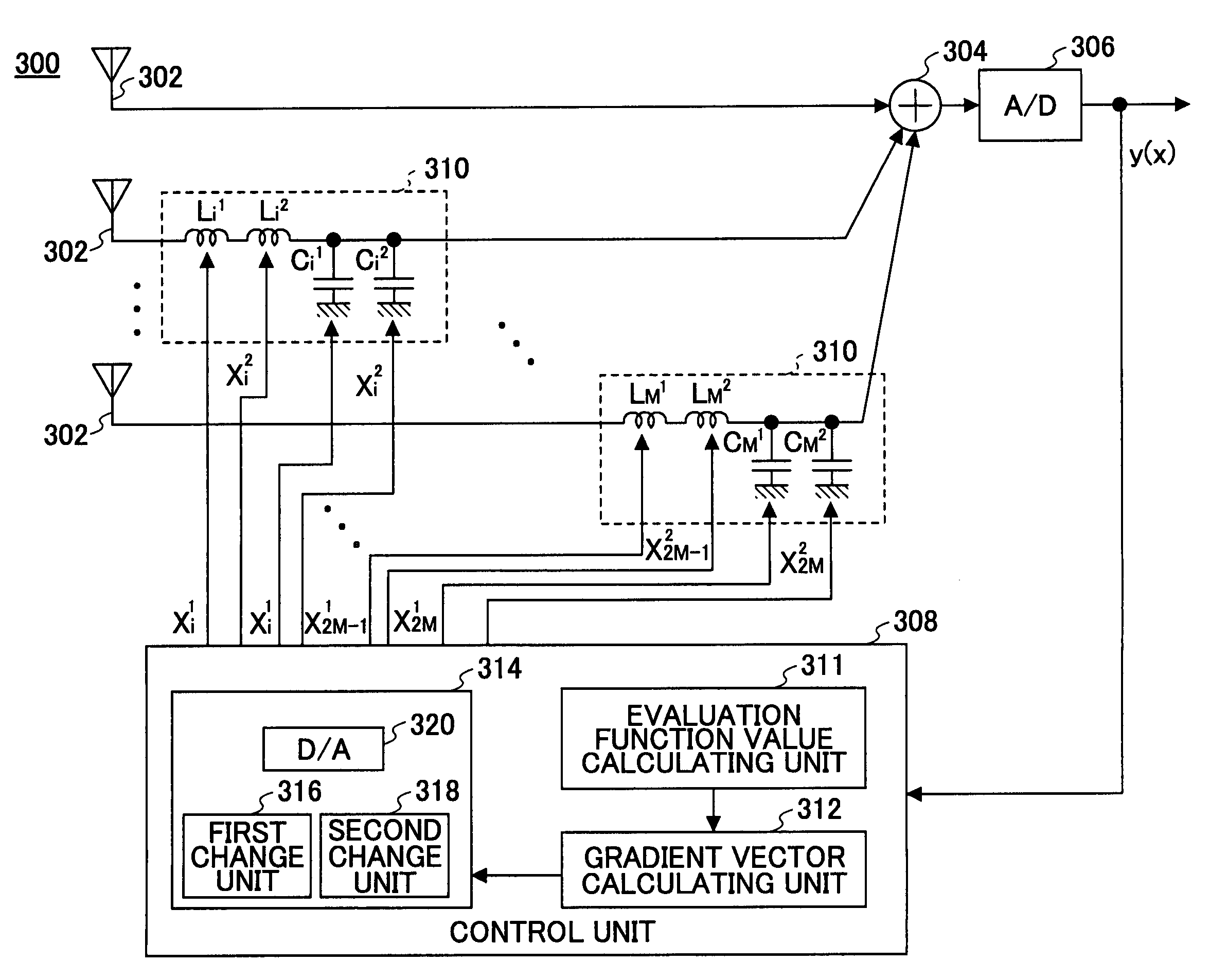
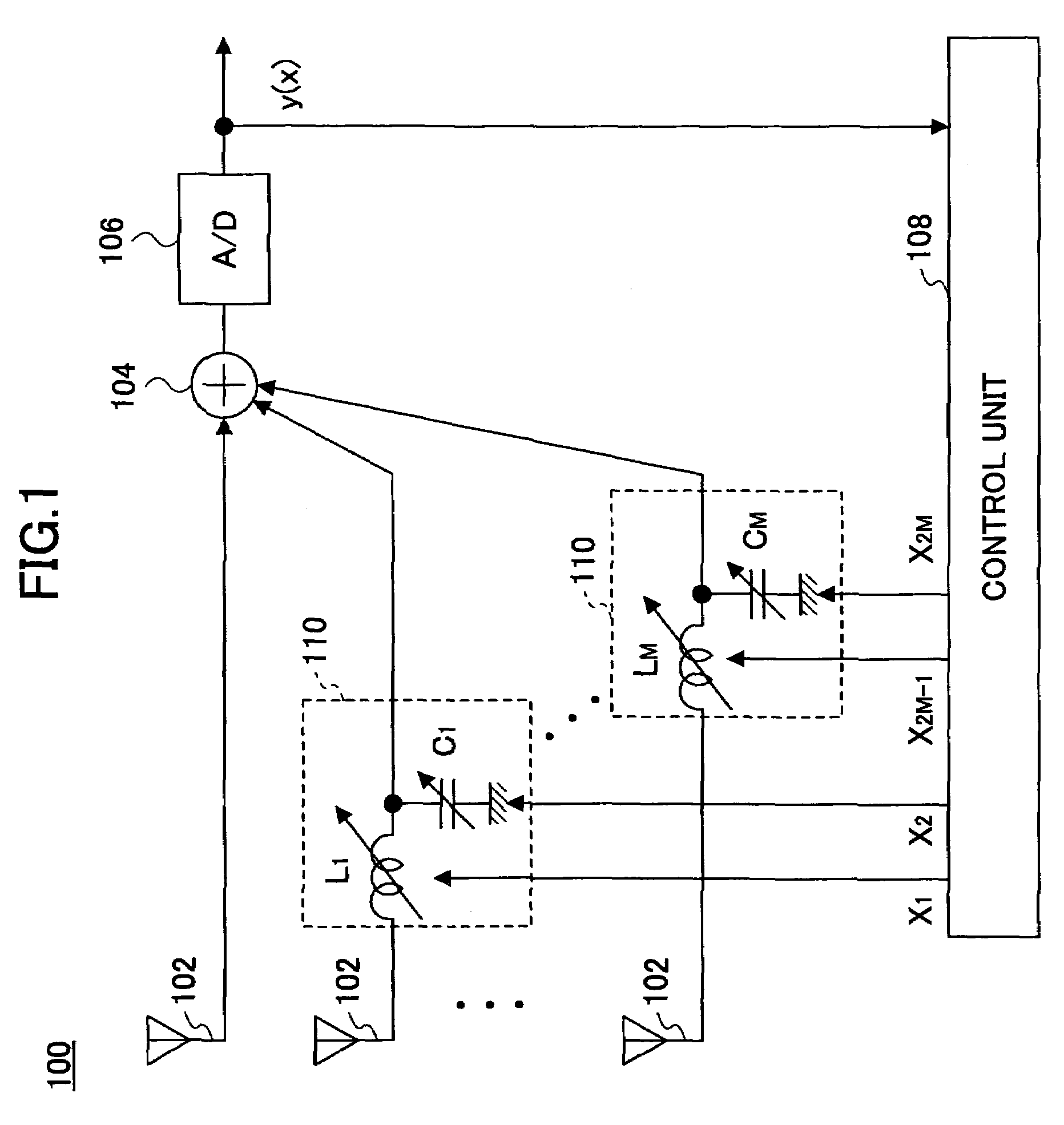
[0037]FIG. 3 is a block diagram showing an example of a control system 300 according to the present invention. The control system 300 serves as a radio frequency (RF) processing type adaptive antenna system, and is a nonlinear system wherein impedances of two or more RF components are unknown, and two or more received signals are combined to form an output signal. The control system 300 includes antenna elements 302, the quantity of which is M+1, and an adder 304 configured to add the signals received by the M+1 antenna elements 302. The output of the adder 304 is provided to an analog-to-digital converter 306. The output of the analog-to-digital converter 306 is provided to a control unit 308.
[0038]To each of M antenna elements 302 out of the M+1 antenna elements 302, a phase shift circuit 310 is connected. The phase shift circuit 310 consists of a first inductor Li1 and a second inductor Li2 connected in series to the antenna element 302, and a first capacitor Ci1 and a second cap...
second embodiment
[0058]FIG. 5 is a block diagram of a control system 500 according to the present invention. The control system 500 serves as a space processing type array antenna system, which is a nonlinear system with two or more antenna elements 502, of which the impedance of the RF component (C) is unknown, wherein a signal received by an antenna element 504 varies with changes of the impedance. The control system 500 includes M antenna elements 502, and the antenna element 504 that is connected to an analog-to-digital converter 506. The output of the analog-to-digital converter 506 is provided to a control unit 508 that is the same as the control unit 308 explained with reference to FIG. 3. Each of the M antenna elements 502 includes a first capacitor Ci1 that functions as the first component, and a second capacitor Ci2 that functions as the second component affecting the directivity of the array antenna. The control unit 508 controls the capacitance of the first and second capacitors Ci1 and ...
third embodiment
[0060]FIG. 6 is a block diagram of a control system 600 according to the present invention. The control system 600 serves as a digital processing type array antenna system, and includes antenna elements 602, each of which further includes a matching circuit 610 for taking impedance matching, and an analog-to-digital converter 606. The matching circuit 610 includes a first capacitor Ci1 that functions as the first component connected in parallel with the antenna element 602, a second capacitor Ci2 that functions as the second component, and a coil Li connected in series to the antenna element 602 (i=1, . . . , M). The impedance of the first and the second component are adjusted based on control signals xi1 and xi2, respectively, provided by a control unit 608.
[0061]According to the present embodiment, the evaluation function value f(x) is calculated based on the total of the signals received through each path of the antenna elements 602. Specifically, the evaluation function value f(...
PUM
 Abstract
Description
Claims
Application Information
 - R&D
- Intellectual Property
- Life Sciences
- Materials
- Tech Scout
- Unparalleled Data Quality
- Higher Quality Content
- 60% Fewer Hallucinations
Browse by: Latest US Patents, China's latest patents, Technical Efficacy Thesaurus, Application Domain, Technology Topic, Popular Technical Reports.
© 2025 PatSnap. All rights reserved.Legal|Privacy policy|Modern Slavery Act Transparency Statement|Sitemap|About US| Contact US: help@patsnap.com


