Information recording medium, method for producing the same, and sputtering target

a technology of information recording medium and sputtering target, which is applied in the field of information recording medium, method for producing the same, and sputtering target, which can solve the problems of poor recording mark storage stability, insufficient recording properties, and small signal amplitude, and achieves high crystallization rate, high crystallization temperature, and large optical variation

Inactive Publication Date: 2010-07-15
PANASONIC CORP
View PDF5 Cites 2 Cited by
  • Summary
  • Abstract
  • Description
  • Claims
  • Application Information

AI Technical Summary

Benefits of technology

[0017]By sputtering the sputtering target of the present invention, it is possible to obtain a phase-change recording l

Problems solved by technology

The result on the L0 was that when the L0 was composed of a composition with satisfactory erasing properties, it exhibited a poor recording mark storage stability and was not usable practically.
The result on the L1 was that when the L0 was composed of a composition with satisfactory erasing properties, it had a small signal amplitude and insufficient recording properties.
Moreover, since the L1 exhibited a poor recording mark storage stability like L0, no optimal composition could be found for it.
A decrease in the crystallization temperature leads to a deterioration of the recording mark storage stability.
However, when the Bi2Te3 concentration was increased, the medium

Method used


Image

  • Information recording medium, method for producing the same, and sputtering target
  • Information recording medium, method for producing the same, and sputtering target
  • Information recording medium, method for producing the same, and sputtering target

Examples


embodiment 1

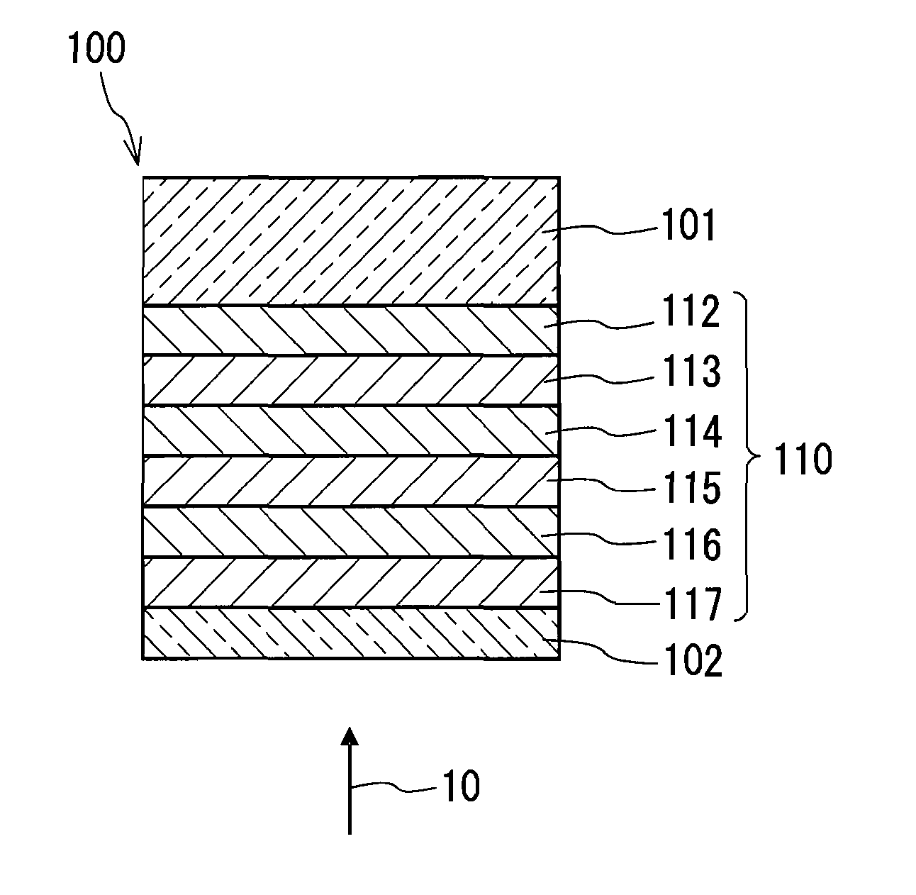
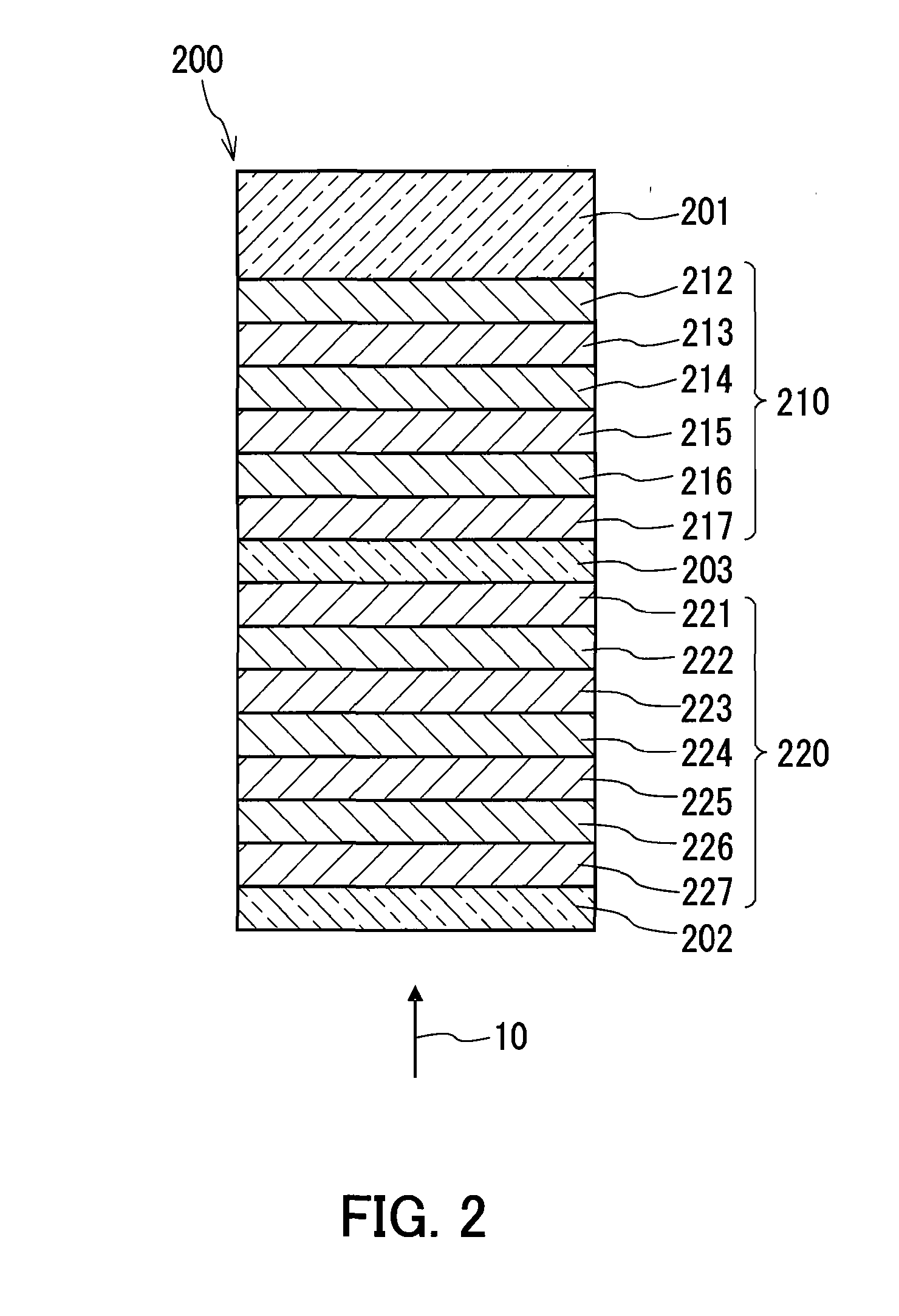
[0037]An example of the information recording medium will be described as Embodiment 1 of the present invention. FIG. 1 shows a partial sectional view of an information recording medium 100 as the example. In the information recording medium 100, an information layer 110 and a transparent layer 102 are formed sequentially on a substrate 101. The information layer 110 is formed of a reflective layer 112, a dielectric layer 113, an interface layer 114, a recording layer 115, an interface layer 116, and a dielectric layer 117 disposed in this order on one surface of the substrate 101.

[0038]The information recording medium 100 can be used as a Blu-ray Disc that has a capacity of 25 GB or more and allows information to be recorded thereon or reproduced therefrom with a laser beam 10 having a wavelength of around 405 nm in a blue-violet region. The laser beam 10 is incident on the information recording medium 100 thus configured from a transparent layer 102 side, and thereby, the recordin...

embodiment 2

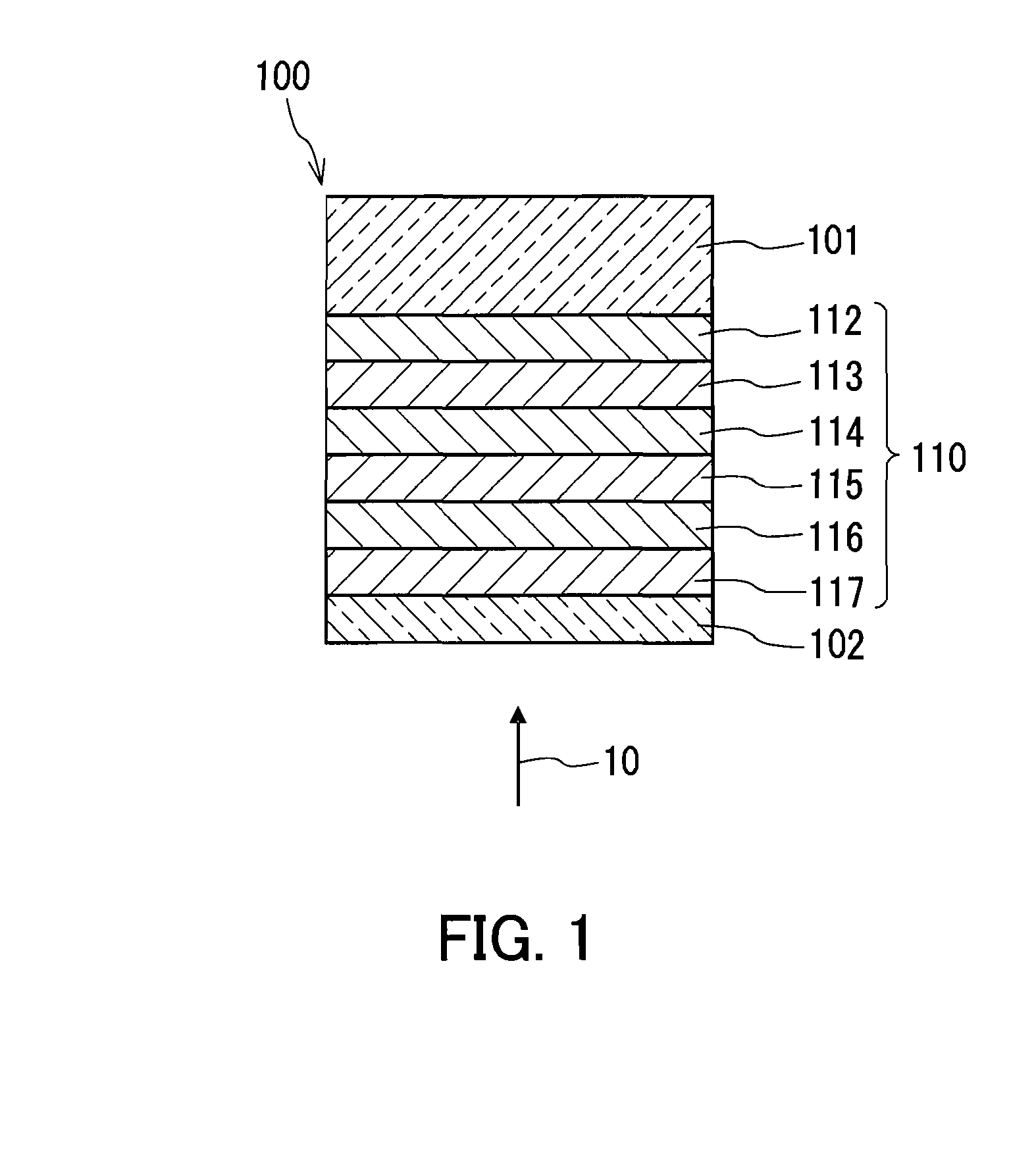
[0103]An example of the information recording medium will be described as Embodiment 2 of the present invention. FIG. 2 shows a partial sectional view of an information recording medium 200 as the example. In the information recording medium 200, a first information layer 210, an interlayer 203, a second information layer 220, and a transparent layer 202 are formed sequentially on a substrate 201. The first information layer 210 is formed of a reflective layer 212, a dielectric layer 213, an interface layer 214, a recording layer 215, an interface layer 216, and a dielectric layer 217 disposed in this order on one surface of the substrate 201. The second information layer 220 is formed of a dielectric layer 221, a reflective layer 222, a dielectric layer 223, an interface layer 224, a recording layer 225, an interface layer 226, and a dielectric layer 227 disposed in this order on one surface of the interlayer 203.

[0104]The laser beam 10 is incident from a transparent layer 202 side...

embodiment 3

[0131]An example of the information recording medium will be described as Embodiment 3 of the present invention. FIG. 3 shows a partial sectional view of an information recording medium 300 as the example. In the information recording medium 300, a first information layer 310, an interlayer 303, a second information layer 320, an interlayer 304, a third information layer 330, and a transparent layer 302 are disposed sequentially on a substrate 301. The first information layer 310 is formed of a reflective layer 312, a dielectric layer 313, an interface layer 314, a recording layer 315, an interface layer 316, and a dielectric layer 317 disposed in this order on one surface of the substrate 301. The second information layer 320 is formed of a dielectric layer 321, a reflective layer 322, a dielectric layer 323, an interface layer 324, a recording layer 325, an interface layer 326, and a dielectric layer 327 disposed in this order on one surface of the interlayer 303. The third inform...


PUM

PropertyMeasurementUnit
Thicknessaaaaaaaaaa
Thicknessaaaaaaaaaa
Energyaaaaaaaaaa

Abstract

An information recording medium (100) of the present invention is an information recording medium that allows information to be recorded thereon by being irradiated with an optical beam or by being applied with electrical energy, and includes at least a recording layer (115) whose phase can change. The recording layer (115) contains antimony (Sb), carbon (C), and a light element (L) having an atomic weight of less than 33. The light element (L) preferably is at least one element selected from B, N, O, Mg, Al, and S. For example, the recording layer (115) may be composed of a material represented by a composition Sb100-x-yCxLy, where the subscripts 100-x-y, x, and y denote composition ratios of Sb, C, and the L in atomic percentage, respectively, and x and y satisfy x+y≦50.

Description

TECHNICAL FIELD[0001]The present invention relates to an information recording medium with respect to which information optically or electrically can be recorded, erased, rewritten, and / or reproduced, and a method for producing the information recording medium. The present invention also relates to a sputtering target to be used for the production.BACKGROUND ART[0002]A standard was established in 2002 for Blu-ray Disc (hereinafter referred to as BD), which has high density and high-capacity, and on and from which information is recorded and reproduced using a blue-violet laser, as a medium for recording high-definition images. There are two types for BD: 25 GB capacity single-layer media (with one information layer on one side); and 50 GB capacity dual-layer media (with two information layers on one side). Particularly, in the dual-layer media, the translucent information layer located closer to a laser beam incident side is called Layer 1 (hereinafter referred to as L1), and the in...

Claims


Application Information

Patent Timeline
IPC IPC(8): B32B3/02C23C14/34G11B7/24035G11B7/24038G11B7/243G11B7/2433G11B7/259
CPCG11B7/2433G11B7/259G11B2007/24304G11B2007/2431G11B2007/24314Y10T428/21G11B2007/24322G11B2007/24324G11B2007/24328G11B2007/25706G11B2007/25715G11B2007/2432
Inventor KOJIMA, RIEYAMADA, NOBORUMATUNAGA, TOSIYUKINISHIHARA, TAKASHI
Owner PANASONIC CORP
Why Eureka
Try Eureka