Parallel processing for programmable wideband digital modulation

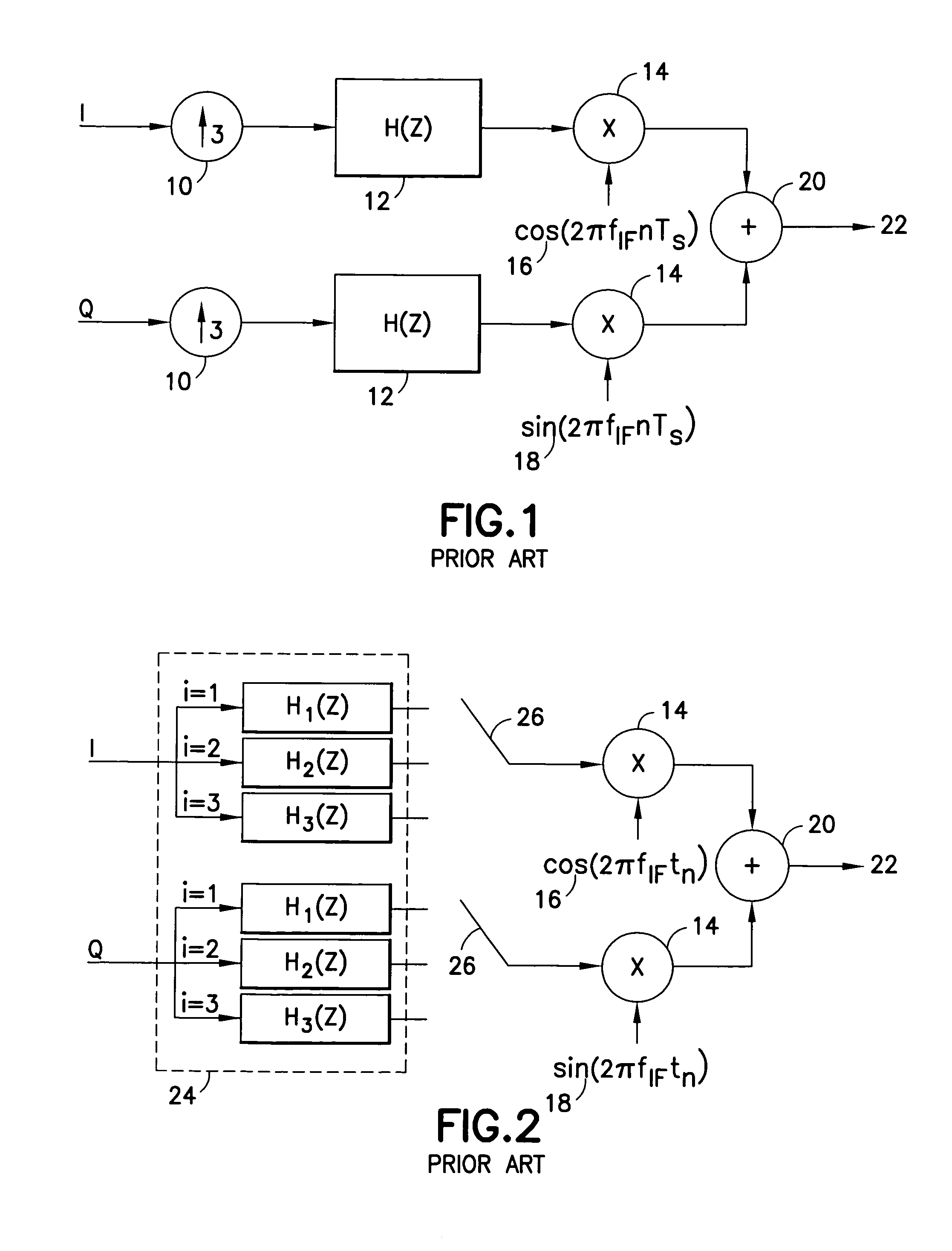
a wideband digital modulation and parallel processing technology, applied in the field of signal processing in wideband programmable digital modems, can solve the problems of inacceptable prior art data rate limitation for wideband programmable modem applications, and the limit of fig. 2 to a symbol rate, and achieve the effect of high data stream ra

Active Publication Date: 2009-04-07
L3 TECH INC
View PDF6 Cites 19 Cited by
  • Summary
  • Abstract
  • Description
  • Claims
  • Application Information

AI Technical Summary

Benefits of technology

[0013]Another aspect of the present invention is a method for digitally sampling and modulating a high rate data stream. The method includes dividing a high rate data input stream into either N bits or 2M symbols, depending upon the particular embodiment of the circuit used to sample and modulate. N is an integer greater than one and M is an integer at least equal to one. Where he input stream is divided into 2M symbols, M symbols are in-phase symbols and M symbols are quadrature symbols. The method further includes upsampling each of the bits or symbols by a factor of k in parallel during a single clock period to provide a continuous output that includes the samples, k being an integer greater than one. The method further includes upconverting and modulating at least some of the samples. For analog upconversion such as via the circuit described above using an FIR filter for upsampling, less than all samples are upconverted. For digital upconversion and modulation such as via the circuit described above using a Nyquist or pulse shaping upsampling filter for upsampling, typically all samples are upconverted and modulated.

Problems solved by technology

Considering the FPGA clock speeds noted above, this prior art limitation on data rate is unacceptable for wideband programmable modem applications.
One drawback to the design of FIG. 1 is that the filter 12 has to run at the sample rate operating on the zeros inserted by the up-sampler 10.
Despite this computational efficiency, the circuit of FIG. 2 remains limited to a symbol rate of one-third the system clock (system clock divided by the up-sampling factor), just as the circuit of FIG. 1.

Method used


Image

  • Parallel processing for programmable wideband digital modulation
  • Parallel processing for programmable wideband digital modulation
  • Parallel processing for programmable wideband digital modulation

Examples


Embodiment Construction

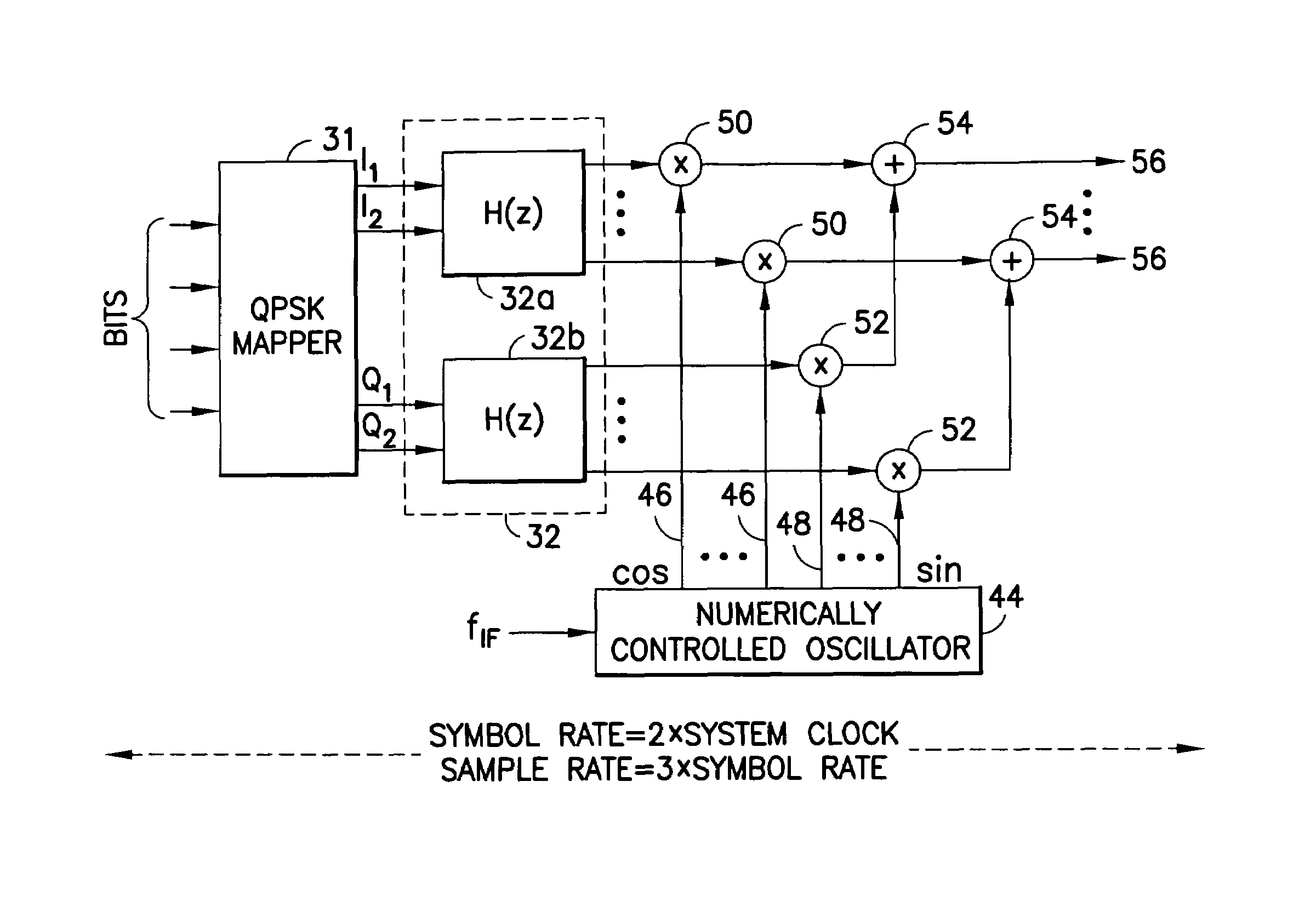
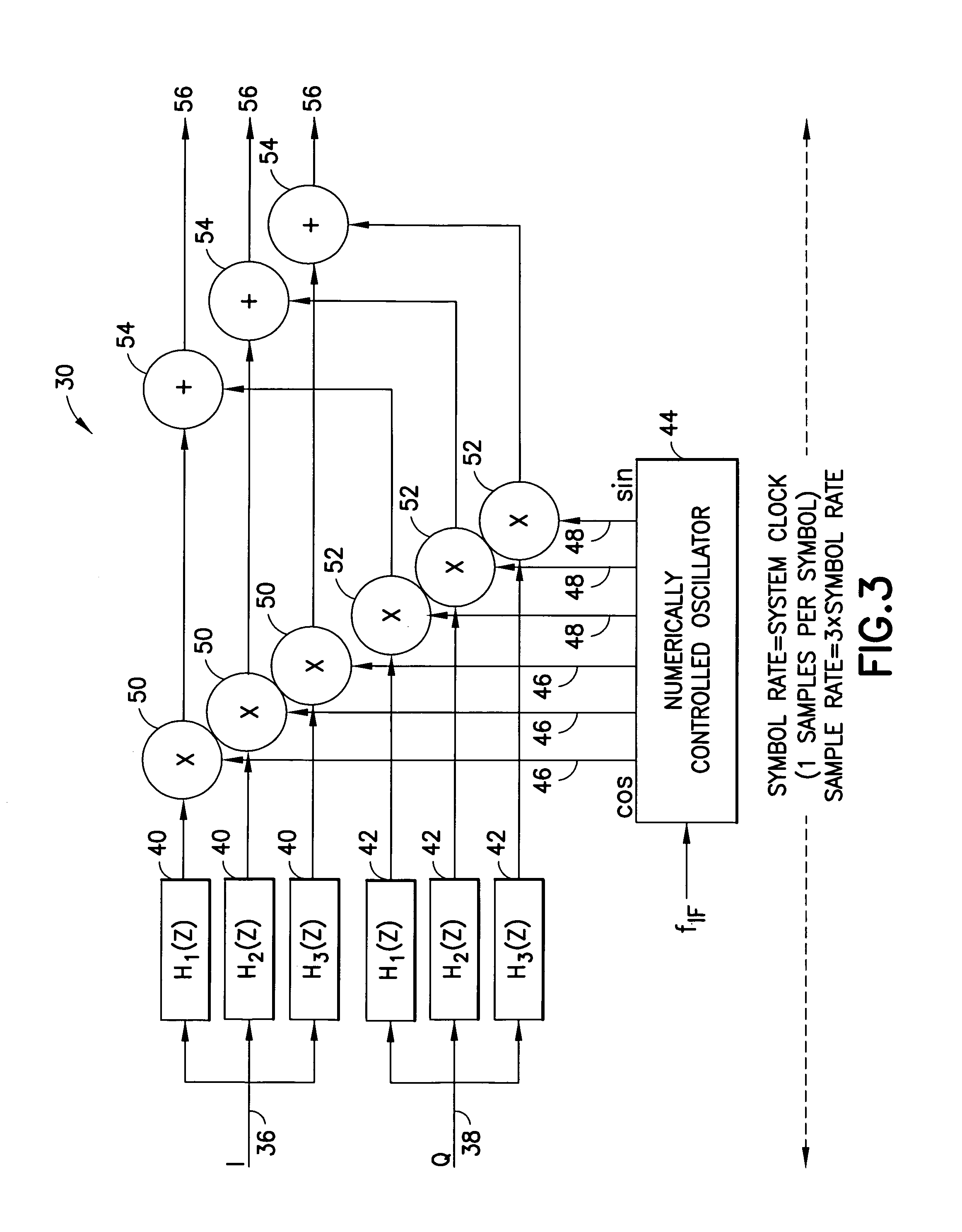
[0008]The foregoing and other problems are overcome, and other advantages are realized, in accordance with the presently preferred embodiments of these teachings. One aspect of the present invention is a circuit for up-sampling a digital data stream. The circuit includes a system clock defining a clock period, a filter, an oscillator, multipliers (designated herein as in-phase and quadrature multipliers for clarity), and adders arranged as follows. The filter has as parallel inputs, during one clock period, M in-phase symbols and M quadrature symbols derived from a high rate data stream, wherein M is an integer greater than or equal to one. The filter outputs in parallel, during one system clock period, k samples from each symbol, wherein k is an integer greater than one. The oscillator outputs 2Mk carrier wave outputs, half of them first carrier wave outputs such as cosine wave signals and half of them second carrier wave outputs such as sine wave signals.

[0009]The in-phase multipl...


PUM


Abstract

A circuit 30 for upsampling and upconverting a high rate signal that is divided into M in phase (I) symbols and M quadrature (Q) symbols. A Nyquist filter 32 upsamples by a factor of k each of the 2M symbols in parallel during one system clock period (CP). The filter 32 has a plurality of 2kM filter components 40, 42, that each provides a continuous output. A plurality of multipliers 50, 52 each upconverts a filter component output with a carrier wave signal 46, 48 that is output from a numerically controlled oscillator 44. A plurality of adders 54 each adds the output of two multipliers 50 to recombine corresponding I and Q samples to output kM samples during a CP. For continuous phase modulation, N parallel bits are input into the filter 32, upsampled in one CP, and accumulated and modulated 82 in parallel in one CP. For analog processing, M (I) and M (Q) symbols are input into an FIR filter 77a, 77b for upsampling, and decimated at a MUX/DAC block 78 for subsequent analog upconversion.

Description

TECHNICAL FIELD[0001]These teachings relate generally to signal processing in wideband programmable digital modems, such as those used in software-defined radios. It is particularly related to parallel processing of an input data signal to upsample the input signal to achieve a data rate out of the circuit greater than or equal to the system clock rate.BACKGROUND[0002]There are a variety of competing modulation techniques for wideband communications, including, for example, Phase Shift Keying (PSK), Amplitude Shift Keying (ASK), Quadrature Amplitude Modulation (QAM), and variations of each, to name a few. There is an increasing need for communication transmitters and receivers that can process and code / decode more than one modulated waveform. For example, various U.S. Government agencies communicate using Common Data Link Class 1 category A and B waveforms, Terrestrial Line of Sight waveform, classified direct downlink waveform, numerous waveforms for civil and military communicatio...

Claims


Application Information

Patent Timeline
Patent Type & Authority Patents(United States)
IPC IPC(8): H04L27/20
CPCH04L27/36H04L27/362
Inventor HADDADIN, OSAMA SAMIGIBSON, JR., L. ANDREWNELSON, DAVID SCOTT
Owner L3 TECH INC
Why Eureka
Try Eureka