
Method and apparatus to create a sound field

a sound field and sound field technology, applied in the field of steering acoustic antennae, can solve the problem of not being able to reproduce the whole signal to be outpu

Active Publication Date: 2009-04-07
YAMAHA CORP
View PDF220 Cites 122 Cited by
  • Summary
  • Abstract
  • Description
  • Claims
  • Application Information

AI Technical Summary

Benefits of technology

The present invention provides a method and apparatus for creating a sound field using an array of output transducers. The technical effects of the invention include addressing the problem of multiple channels output from a single array of transducers resulting in auditory out of synchronization, providing temporal correspondence between pictures and sound channels, and allowing different sound channels to have different directivity. Additionally, the invention allows for the use of window functions to apply different window functions to different sound channels, resulting in a more desirable sound field and easier adjustment of volume for each sound channel.

Problems solved by technology

Each transducer is capable of creating a sound pressure pulse and is not able to reproduce the whole of the signal to be output.

Method used


Image

  • Method and apparatus to create a sound field
  • Method and apparatus to create a sound field
  • Method and apparatus to create a sound field

Examples


Embodiment Construction

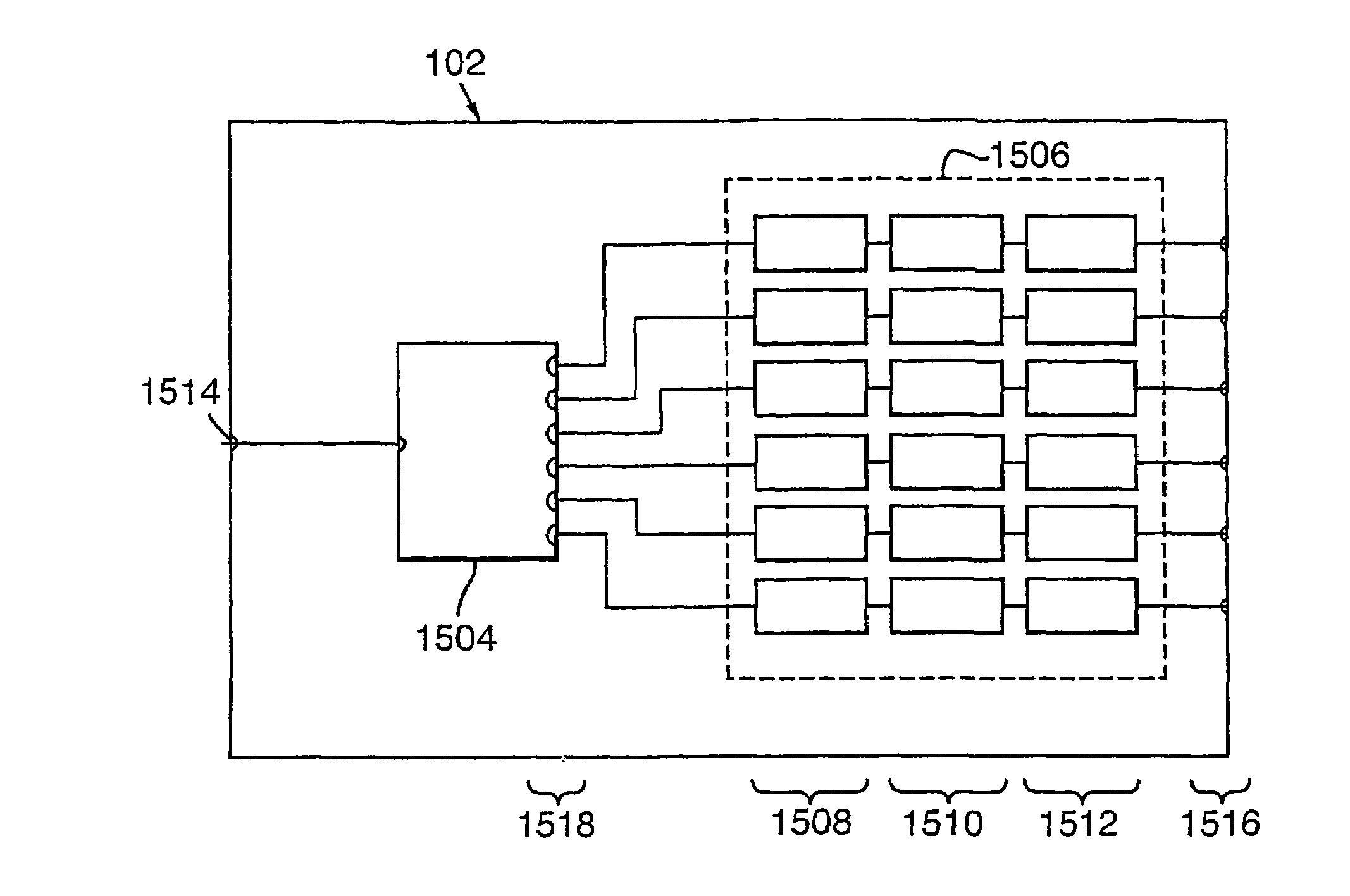
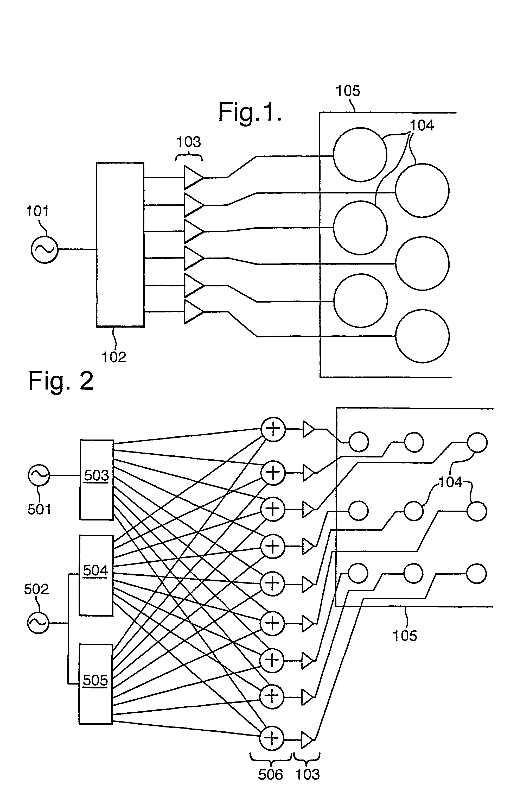
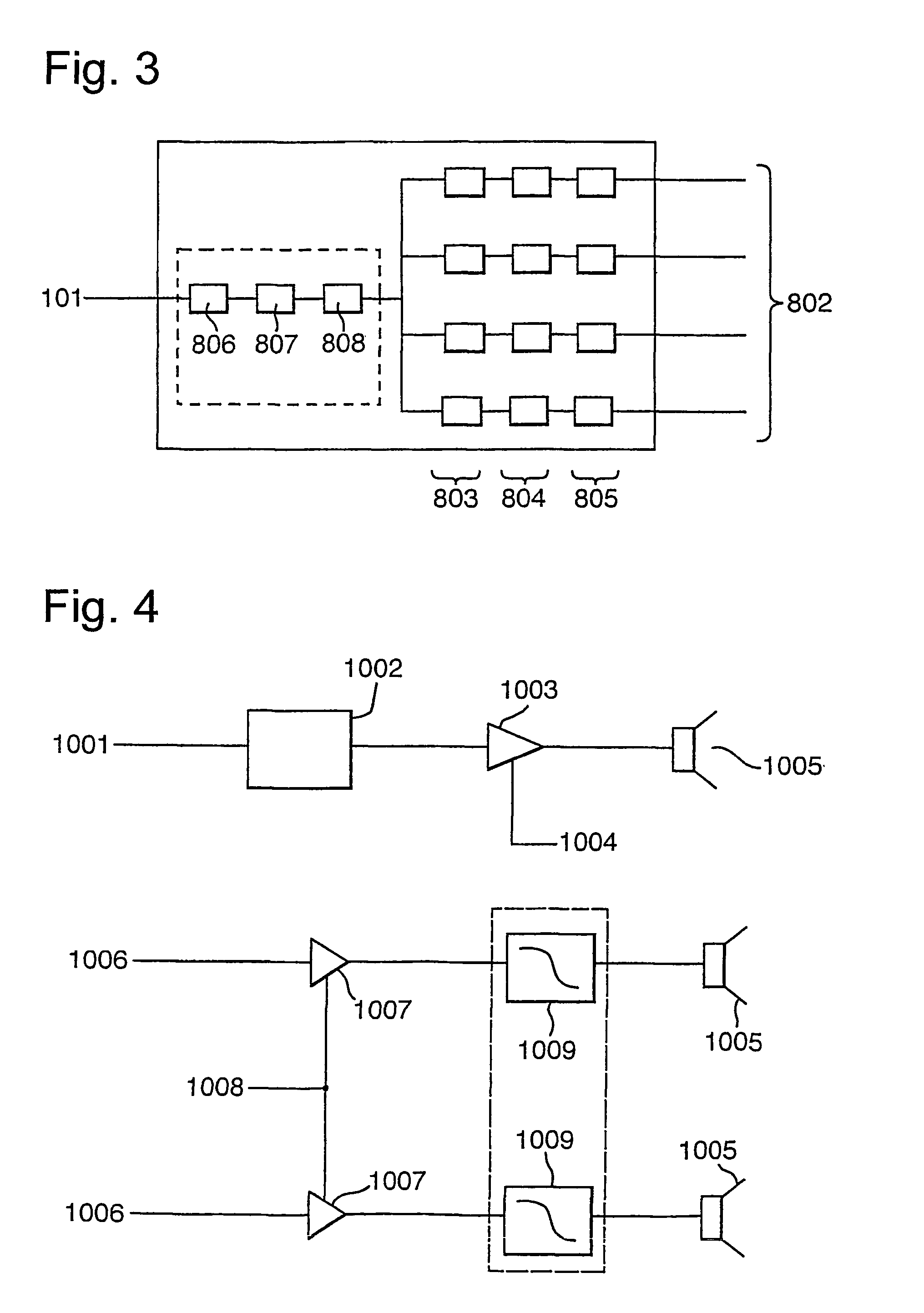
[0132]The description and Figures provided hereinafter necessarily describe the invention using block diagrams, with each block representing a hardware component or a signal processing step. The invention could, in principle, be realised by building separate physical components to perform each step, and interconnecting them as shown. Several of the steps could be implemented using dedicated or programmable integrated circuits, possibly combining several steps in one circuit. It will be understood that in practice it is likely to be most convenient to perform several of the signal processing steps in software, using Digital Signal Processors (DSPs) or general purpose microprocessors. Sequences of steps could then be performed by separate processors or by separate software routines sharing a microprocessor, or be combined into a single routine to improve efficiency.

[0133]The Figures generally only show audio signal paths; clock and control connections are omitted for clarity unless ne...


PUM


Abstract

The invention generally relates to a method and apparatus for taking an input signal, replicating it a number of times and modifying each of the replicas before routing them to respective output transducers such that a desired sound field is created. This sound field may comprise a directed beam, focussed beam or a simulated origin. In a first aspect, delays are added to sound channels to remove the effects of different travelling distances. In a second aspect, a delay is added to a video signal to account for the delays added to the sound channels. In a third aspect, different window functions are applied to each channel to give improved flexibility of use. In a fourth aspect, a smaller extent of transducers is used top output high frequencies than are used to output low frequencies. An array having a larger density of transducers near the centre is also provided. In a fifth aspect, a line of elongate transducers is provided to give good directivity in a plane. In a sixth aspect, sound beams are focussed in front or behind surfaces to give different beam widths and simulated origins. In a seventh aspect, a camera is used to indicate where sound is directed.

Description

FIELD OF THE INVENTION[0001]This invention relates to steerable acoustic antennae, and concerns in particular digital electronically-steerable acoustic antennae.BACKGROUND TO THE INVENTION[0002]Phased array antennae are well known in the art in both the electromagnetic and the ultrasonic acoustic fields. They are less well known, but exist in simple forms, in the sonic (audible) acoustic area. These latter are relatively crude, and the invention seeks to provide improvements related to a superior audio acoustic array capable of being steered so as to direct its output more or less at will.[0003]WO 96 / 31086 describes a system which uses a unary coded signal to drive a an array of output transducers. Each transducer is capable of creating a sound pressure pulse and is not able to reproduce the whole of the signal to be output.SUMMARY OF THE INVENTION[0004]A first aspect of the present invention addresses the problem that can arise when multiple channels are output by a single array of...

Claims


Application Information

Patent Timeline
Patent Type & Authority Patents(United States)
IPC IPC(8): H04R5/00H04R5/02H04N5/232G10K15/04H04R1/26H04R1/40H04R3/12H04S1/00H04S3/00H04S7/00
CPCF41H13/0081G10K15/04H04R1/403H04R3/12H04S3/00H04R1/26H04R2201/401H04R2203/12H04R2205/022H04S1/002H04S3/002
Inventor HOOLEY, ANTHONYTROUGHTON, PAUL THOMASGOUDIE, ANGUS GAVINEASTON, MARK GEORGEBIENEK, IRVING ALEXANDERDAVIES, JAMESRYAN, DAMON THOMASWINDLE, PAUL RAYMOND
Owner YAMAHA CORP
Learn More