
Implant device used in minimally invasive facet joint hemi-arthroplasty

a technology for facet joint hemi-arthroplasty and implant device, which is applied in the field of implant device for minimally invasive spine surgery, can solve the problems of non-surgical symptomatic treatment, prolonged recovery time of present art, and uncertain outcomes, and achieves less traumatic, less recovery time, and minimal invasive

Inactive Publication Date: 2009-04-14
MINSURG INT INC
View PDF162 Cites 158 Cited by
  • Summary
  • Abstract
  • Description
  • Claims
  • Application Information

AI Technical Summary

Benefits of technology

[0007]The present invention provides a pre-made pre-shaped metallic implant for use in minimally invasive spine surgery. The use of a pre-shaped metallic overlay of this invention for facet joint resurfacing of diseased, painful, deteriorated or overstressed joints offers three distinct advantages over larger prosthetic implants; namely, (1) using a thin metallic overlay allows for minimally invasive insertion that is safer, less traumatic and requires far less recovery time compared to a prosthetic; (2) the overlay does not require the use of cements, pedicle screws or other fixation methods that can work their way loose over time; and, (3) the implant has two fins or blades to provide lateral stability and two teeth to provide temporary fixation and a rough or porous inner surface amenable to bone in growth providing permanent natural fixation. The implant also has a polished outside that allows for smooth, natural, pain free articulation of the joint.
[0008]The implant is specifically designed for use in an arthroscopic type portal for standalone procedures, but also may be used in classic open surgery. This implant provides a unique, stronger and superior resurfacing and may be used for, but not limited to: (1) an adjunct to instrumented vertebral fusion when implanted in the two facet joints immediately above and below the two joints adjoining the instrumentation thereby eliminating the risk of collateral post-operative facet joint pain resulting from additional stress placed on facet joints, (2) when used to resurface adjoining facet joints directly above and below a disk replacement by eliminating the risk of collateral post-operative facet joint pain resulting from additional stress placed on facet joints by the disk replacement, and, (3) as a stand along treatment for diseased, painful or deteriorated facet joints.
[0009]The invention accomplishes its goal of resurfacing a painful, diseased or deteriorated spinal facet joints by providing a resurfacing implant to replace the joint surface with a small metal on bone overlay. The overlay, constructed of cobalt chrome or such other biocompatible metal or metallic alloy appropriate for joint hemi-arthroplasties, is one of several sizes for various segments of the spine, similarly sized for different facet joints or groups of joints in the spine and are attached to the joint using a straightforward process without the need for screws or cements. The facet joints may be accessed using an arthroscopic type portal eliminating the need for open surgery, hospitalization and long recovery periods. The procedure also may be performed as an adjunct to other procedures such as instrumented fusion and disc replacement in a traditional open surgery. Because the side of the implant that attaches to bone is porous, the bone heals onto it, permanently fixing it into place. A uniquely designed set of blades and teeth provides temporary fixation to the joint and prevents migration. A crimping system allows the implant to be fixed into place, holding it firmly until bone in growth is complete. The side making contact with the joint is highly polished providing a smooth, virtually frictionless surface that undergoes virtually no wear and tear. The inside is rough or porous providing an amenable surface for bone in growth.

Problems solved by technology

In general, the present art requires prolonged recovery times, from six to twenty-four months, and offers uncertain outcomes.
High risk equates to frequent litigation, which forces non-surgical symptomatic treatment while the disease or consequences of injury progressively worsen.

Method used


Image

  • Implant device used in minimally invasive facet joint hemi-arthroplasty
  • Implant device used in minimally invasive facet joint hemi-arthroplasty
  • Implant device used in minimally invasive facet joint hemi-arthroplasty

Examples


Embodiment Construction

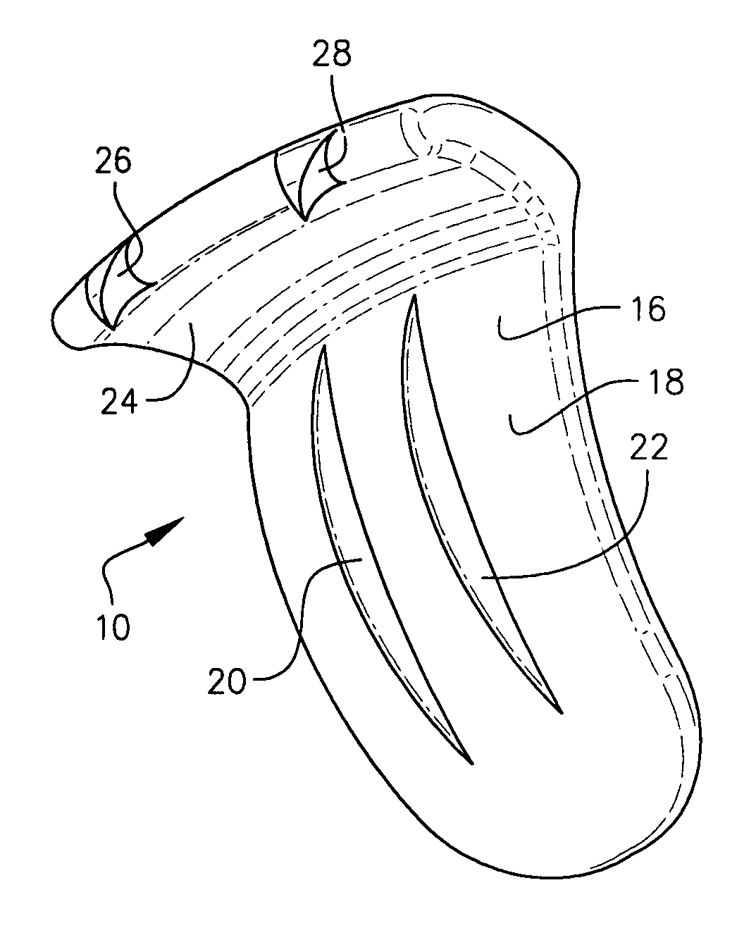
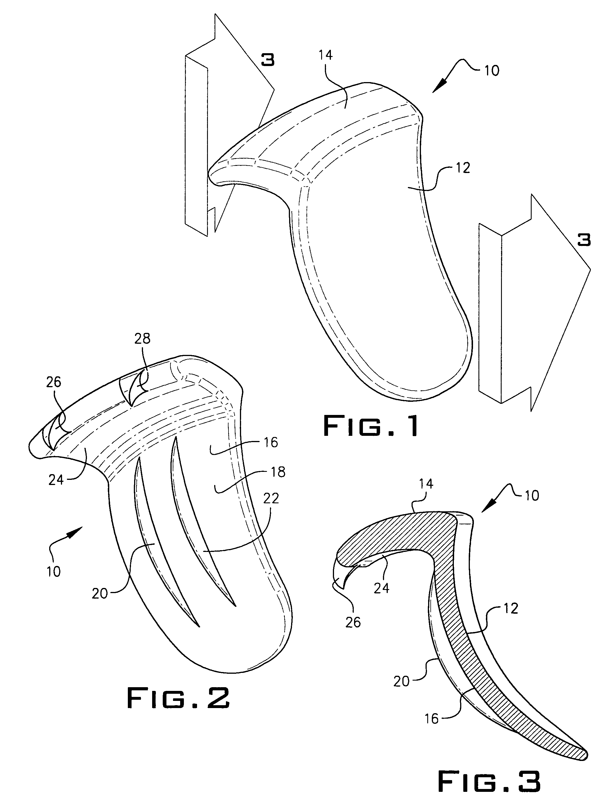
[0021]Referring to FIG. 1, the prosthetic implant 10 of this invention has a highly polished concave outside back portion 12 and a convex highly polished surface on a top portion 14. The highly polished surface is a cobalt-chrome alloy, a titanium alloy or other biologically acceptable material capable of forming a smooth highly polished surface. Referring to FIG. 2, an inside convex surface is textured 18 to encourage new bone growth and adhesion. Blades 20 and 22 attached to inside surface 16 bite into bone to promote adhesion. The bottom surface 24 of the top portion of implant 10 is concave to fit tightly over a bone as shown in FIGS. 7 and 8. Teeth26 and 28 are used for imbedding into adjacent bone to prevent movement of implant 10.

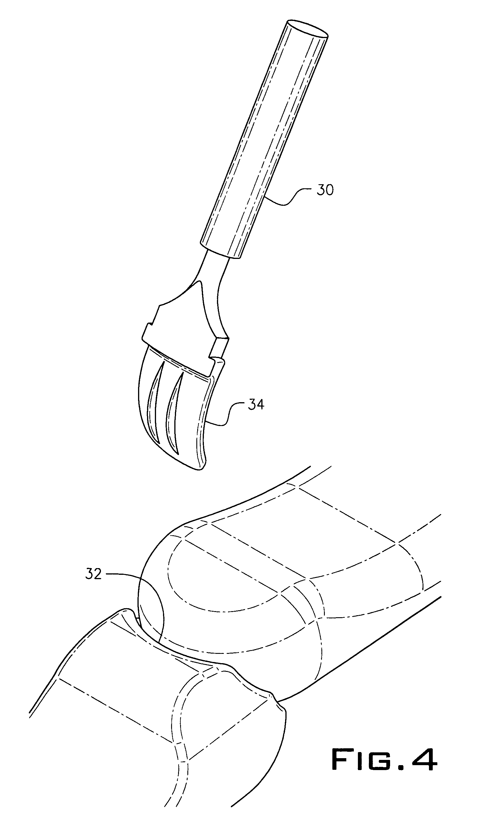
[0022]Prior to imbedding the implant in the facet joint 32, a preparation tool 30 is used to slightly spread the joint 32. Tool end 34 is inserted into the joint 32 to provide sufficient space for inserting implant 10 into joint 32 as seen in FIGS. 7...


PUM


Abstract

A metallic inverted L-shaped implant is used to resurface the superior facet of the inferior vertebrae limited to the facet joints located on the spine, Occiput-C1 through L5-S1. The metallic implant is highly polished on its exterior and textured on its interior surface. It is mechanically crimped in place without the use of cement or pedicle screws. Permanent fixation occurs when bone in-grows onto a rough, porous surface on the inside of the implant. The implant employed in a hemi-arthroplasty method resurfaces half of the facet joint to provide for smooth, pain free joint articulation in deteriorated or diseased spinal facet joints without the need for major surgery or rehabilitation at considerably less risk to the patient.

Description

PRIOR APPLICATION[0001]This application is a continuation-in-part from application Ser. No. 10 / 992,746, filed Nov. 22, 2004 now abandoned.BACKGROUND OF THE INVENTION[0002]The present invention relates generally to a device for use in minimally invasive spine surgery. More particularly, it refers to a pre-made, pre-shaped metallic implant implanted using an arthroscopic type portal or classic open surgical method to achieve a spinal facet joint hemi-arthroplasty to resurface any or all of the forty-eight superior facets of the inferior Occiput-C1 through L5-S1 vertebrae.[0003]In the United States alone, about 10% of the entire population will suffer from back pain sometime in the next twelve months. More people will contract back pain in the next year than any other injury or disease except the common cold and flu. About one-third will not recover and have to live with persistent, disabling symptoms. The number is cumulative year after year.[0004]One of the root causes of back pain, ...

Claims


Application Information

Patent Timeline
Patent Type & Authority Patents(United States)
IPC IPC(8): A61B17/70
CPCA61F2/4405A61F2002/30841A61F2002/30884A61F2002/4635A61F2310/00029
Inventor PETERSEN, DAVID A.
Owner MINSURG INT INC
Learn More