Polygonal cylinder array antenna

a phased array and polygonal technology, applied in the field ofradar systems, can solve the problems of rotary joint and coupler, unsatisfactory radar orientation options, and undesirable requirements for heavy mechanical components

Inactive Publication Date: 2009-04-21
LOCKHEED MARTIN CORP
View PDF41 Cites 72 Cited by
  • Summary
  • Abstract
  • Description
  • Claims
  • Application Information

AI Technical Summary

Problems solved by technology

The airship's distinctive skin materials and craft shape often challenge equipment designers in their efforts to effectively mount information gathering instrumentation, such as radar systems.
Consequently, radar orientation with respect to the airship provides few satisfactory options.
Disadvantages associated with such an approach include the undesirable requirements for heavy mechanical components, including a rotary joint and coupler that are incompatible with lightweight airship applications.
Still further, the aforementioned planar phased array cannot provide instantaneous coverage over 360°.
Moreover, such a solution would suffer significant beamsteering gain loss (e.g. >9 dB) near coverage limits, thus, severely compromising overall operational performance.
Numerous problems exist with this approach as well.
In addition, non-uniform element-to-element separations degrade the shape, gain, and sidelobes of the electronically scanned beam.
Furthermore, range coverage and azimuth beamwidth are non-uniform in azimuth, as the projected aperture changes significantly as a function of azimuth.
Accurate beamforming and shaping is therefore difficult because the airship surface expands and contracts significantly due to air density and temperature variations and tends to undulate or flutter due to airflow.
Still further, manufacturing and construction costs associated with the above approaches are high, due at least in part because the variable surface curvature requires the sub-panels constituting the array be of many different shapes and designs, creating adherence problems analogous to the well publicized space shuttle tiling problem.
Other problems associated with the aforementioned approaches include complicated power and signal distribution, as different parts of the array may be hundreds of meters apart.
Changing airship shapes also make calibration difficult, particularly with regard to the difficulty or inability to inject test signals into the antenna elements in the above surface-conformal approach.

Method used


Image

  • Polygonal cylinder array antenna
  • Polygonal cylinder array antenna
  • Polygonal cylinder array antenna

Examples


Embodiment Construction

[0032]In the figures to be discussed, the circuits and associated blocks and arrows represent functions of the process according to the present invention which may be implemented as electrical circuits and associated wires or data busses, which transport electrical signals. Alternatively, one or more associated arrows may represent communication (e.g., data flow) between software routines, particularly when the present method or apparatus of the present invention is a digital process. In the embodiments of the invention disclosed herein, the airships are gas filled dirigibles, however, the invention as disclosed is not limited in its application to dirigibles, but may be employed in other types of aircraft, satellites or stationary ground radar systems.

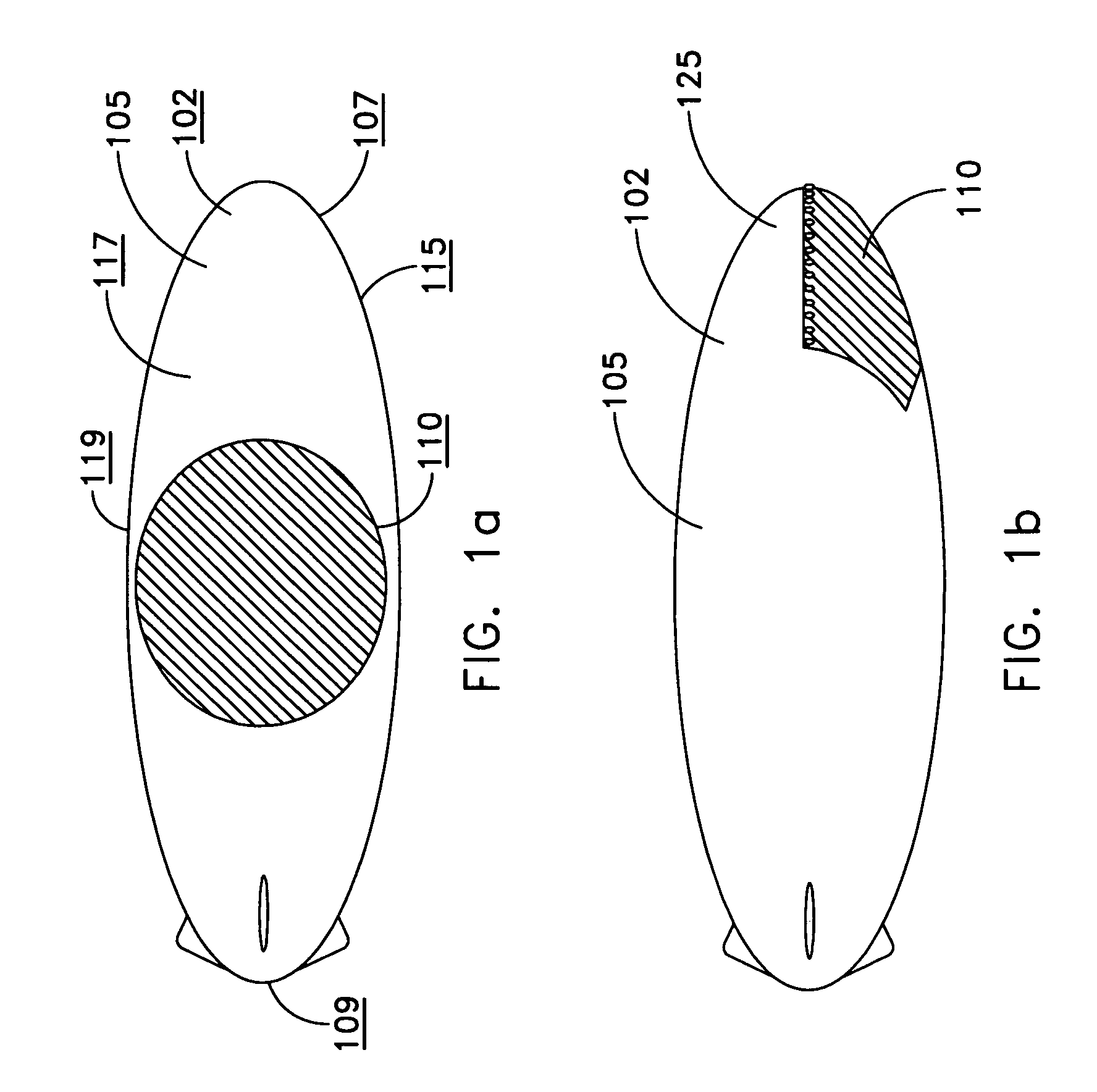
[0033]As previously discussed with regard to FIG. 1a and FIG. 1b, an airship 102 surface curvature 117 changes continuously over an entire surface 115, and an antenna array 110 on such a doubly-curved surface must continuously change ...


PUM


Abstract

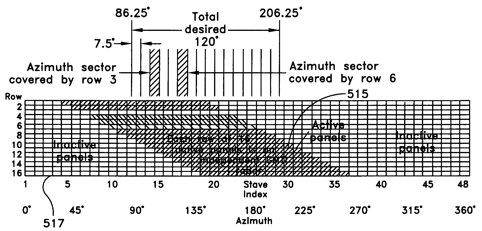
A polygonal cylindrically shaped phased array antenna forming a radar has an active aperture that focuses in any of one or more angular azimuth directions without inertia. It further includes adjacent multiple similar polygonal staves joined along their vertical edges to form a right regular polygonal cylinder. Each stave is further decomposed into flat panels, wherein each panel has a plurality of antenna elements positioned in a regular rectangular or triangular lattice. Each panel contains a beam forming network that electronically forms and steers an electromagnetic beam for purposes of transmission and subsequent reception. The panels optionally may operate as autonomous radars which when coherently combined form multiple larger antenna apertures, each capable of operating autonomously. A switching network allows transmit power and all requisite radar and control signals to be sent to and received from a selected set of panels anywhere on the polygonal cylinder.

Description

RELATED APPLICATION[0001]This application claims priority to U.S. Provisional Application No. 60 / 699,621, filed Jul. 15, 2005, the subject matter thereof incorporated by reference herein in its entirety.FIELD OF THE INVENTION[0002]This application relates generally to radar systems, and more particularly to cylindrical phased array radar antennas useful for airborne applications.BACKGROUND OF THE INVENTION[0003]In both military and civilian terrain mapping and object tracking there exists a need to enable coverage of an earth-fixed azimuth sector from high-altitude airships whose orientation continuously changes. The high-altitude airships are generally gas filled dirigibles or blimps that have shapes designed for maximizing their aerodynamic performance such as lift, maneuverability and stationary or forward movements. The airship's distinctive skin materials and craft shape often challenge equipment designers in their efforts to effectively mount information gathering instrumentat...

Claims


Application Information

Patent Timeline
Patent Type & Authority Patents(United States)
IPC IPC(8): G01S13/52G01S5/02H01Q1/28H01Q21/00H01Q3/00G01S19/25
CPCG01S13/424H01Q1/28H01Q21/20G01S2013/0254G01S2013/0272
Inventor WASIEWICZ, RICHARDSTOCKMANN, PETER H.
Owner LOCKHEED MARTIN CORP
Why Eureka
Try Eureka