Structured shelf

a shelf and structure technology, applied in the field of structured shelves, can solve the problems of reducing the density of the shelf per shelf, the inability to shorten the roundabout route, and the bending radius

Active Publication Date: 2009-04-21
FUJITSU LTD
View PDF19 Cites 67 Cited by
  • Summary
  • Abstract
  • Description
  • Claims
  • Application Information

AI Technical Summary

Benefits of technology

[0025]The present invention has been developed with a view to eliminating these problems, and it is therefore an object of the invention to provide a structured shelf capable of inserting / removing units connected to a plurality of cables each having a limitation on bending radius and of conducting extra-cable handling within a limited spatial range, inserting / removing a desired unit into / from a shelf in a state where a cable is in an active condition and improving a shelf mounting density per rack.

Problems solved by technology

Yet additionally, for increasing the number of shelves (mounting density) storable in one rack, there is a need to achieve the size reduction of the rack and the shelf since limitation is imposed on the vertical width of each shelf.
Although it can be considered that the four optical cables 9 take a roundabout route so as not to intersect with the drawing direction of the unit A, this is difficult because there are the limitations on the bending radius of the optical cables 9.
Moreover, a method of shortening the roundabout route length is unemployable because the bending radius of the optical cable 9 becomes smaller than the allowable bending radius (for example, R30).
Therefore, the method of using a roundabout route extremely reduces the shelf mounting density per rack and makes it difficult to set the bending radius of the optical cable 9 at a value below the allowable bending radius, thereby extremely lowering the degree of freedom on wiring.
Still additionally, the method of using the extra-portion handling area requires an extra-portion handling operation for each shelf 100, which makes it difficult to efficiently mount a plurality of shelves 100 in one rack, thus leading to a disadvantage in terms of mounting density per rack.
Yet additionally, when the units A and B are forcibly drawn out from the shelf 100, difficulty is experienced in exhibiting the performance of the optical cable 9 sufficiently.
Moreover, the laying of the optical cable 9 requires an extremely special devices and a repairing operation asks an operator for a high skill and, hence, a quick repairing operation becomes difficult and a high repairing cost becomes necessary, which can result in the suspension of operations of the optical transmission network.
This also suffer problems similar to those mentioned above.

Method used


Image

  • Structured shelf
  • Structured shelf
  • Structured shelf

Examples


first embodiment

(A) Description of First Embodiment of the Present Invention

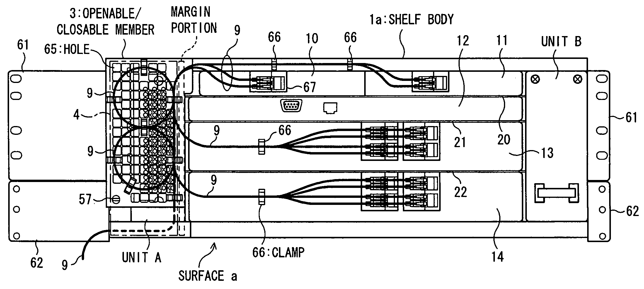
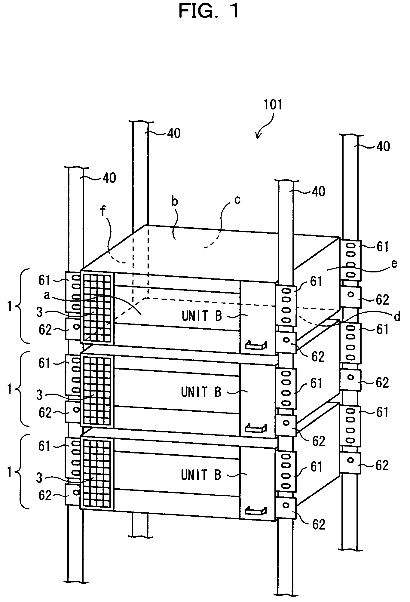
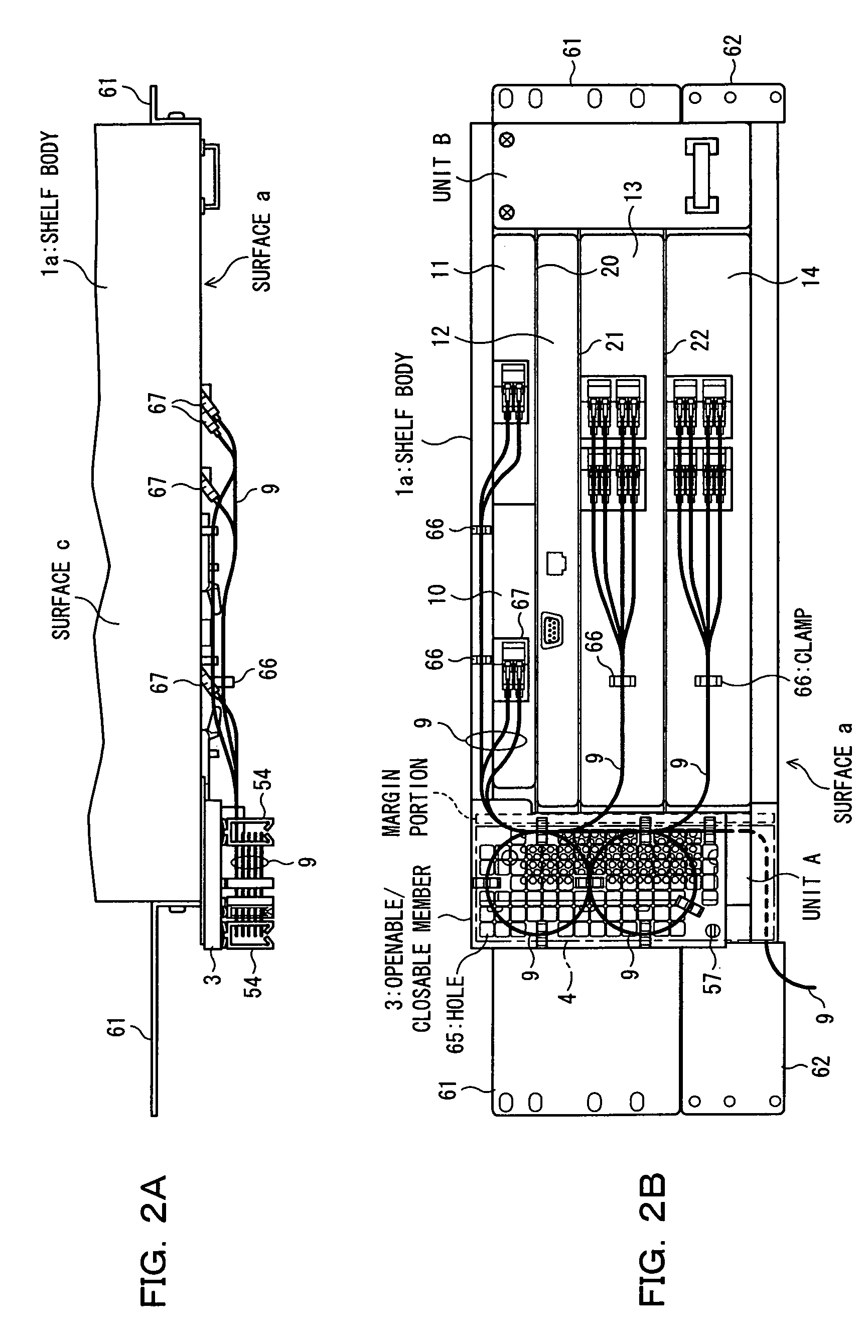
[0069]A structured shelf according to the present invention is mounted in, for example, each station of an optical transmission network or one or a plurality of line accommodating units (each of which will hereinafter be referred to as a shelf unless otherwise specified particularly) provided in an in-like amplifier. Each shelf is for conducting interface processing on various types of transmission signals such as optical signal, packet signal and subscriber's line signal. Concretely, it is designed to carry out optical signal processing (physical processing including optical demultiplexing, optical multiplexing and optical amplification), termination processing (optical-electrical mutual conversion, and others), transfer processing (packet transmission / reception, packet multiplexing / demultiplexing, and others) and mutual format conversion in each line, and other processing. In each station, a plurality of shelves are store...

second embodiment

(B) Description of Second Embodiment of the Present Invention

[0115]FIG. 13 is a front perspective view illustratively showing a shelf according to a second embodiment of the present invention. In a shelf 300 shown in FIG. 13, in place of the employment of the openable / closable members 3 and 3a shown in FIGS. 9 and 10B, an openable / closable member 5 is provided in front of a unit A to be openable and closable. This openable / closable member 5 is constructed as an openable / closable member having a convex configuration raised outwardly with respect to the second opening portion 7. That is, the openable / closable member 5 has a configuration inflated in the removing direction of the unit A. Moreover, a plurality of clips 54 are set on a surface of the openable / closable member 5.

[0116]In this case, the construction of the openable / closable member 5 being provided within a plane in the internal width range of the shelf set to be smaller than a prescribed horizontal length of the rack 101 (s...


PUM


Abstract

In an optical transmission node, a plurality of shelves, respectively connected to a plurality of optical cables having limitations on bending radius, are stored in one rack of the node. In a shelf body thereof, the first and second opening portions are made in a front surface, and an extra-cable looping device loops an extra portion of the optical cable, further a moving mechanism is provided for moving the extra-cable looping device to avoid a space occupied by the units in a state removed from the second opening portion, this enables extra-cable handling within a limited spatial range and the insertion / removal of the units having various functions from the shelf in a state where the cable is active and further the improvement of a shelf mounting density per rack.

Description

BACKGROUND OF THE INVENTION[0001](1) Field of the Invention[0002]The present invention relates to a structured shelf suitable in a case in which a plurality of shelves respectively connected to a plurality of cables, for example, having limitations on bending radius are accommodated in one rack, and more particularly to a structured shelf suitable in a case in which a plurality of line accommodating units respectively connected to a plurality of optical cables having limitations on allowable bending radius are stored in one rack provided in a transmission station.[0003](2) Description of the Related Art[0004]In general, a transmission signal such as optical signal or electric signal is wire-transmitted in a state where a plurality of transmission cables, such as optical cables or electric cables, or transmission mediums are collectively hardwired in a transmission station (which will be referred to hereinafter as a station or node; for example, transmission terminal station, repeati...

Claims


Application Information

Patent Timeline
Patent Type & Authority Patents(United States)
IPC IPC(8): G02B6/00
CPCG02B6/4452
Inventor ARAKI, HIDEOKANASAKI, KATSUMIIMABAYASHI, HIROFUMITOSHIMITSU, KENJINAKANISHI, YUICHI
Owner FUJITSU LTD
Why Eureka
Try Eureka