Parasitic load control system for exhaust temperature control

a load control and temperature control technology, applied in the direction of electric control, machines/engines, fuel injecting pumps, etc., can solve the problems of increasing the temperature of the exhaust produced by the engine, increasing etc., to increase the parasitic load on the engine, increase the temperature of the exhaust produced, and increase the load on the fuel pumping mechanism

Active Publication Date: 2009-04-28
CATERPILLAR INC
View PDF21 Cites 16 Cited by
  • Summary
  • Abstract
  • Description
  • Claims
  • Application Information

AI Technical Summary

Benefits of technology

[0011]In one aspect, the present disclosure is directed to a parasitic load control system. The system may include an exhaust producing engine and a fuel pumping mechanism configured to pressurize fuel in a pressure chamber. The system may also include an injection valve configured to cause fuel pressure to build within the pressure chamber when in a first position and allow injection of fuel from the pressure chamber into one or more combustion chambers of the engine when in a second position. The system may further include a controller configured to independently regulate the pressure in the pressure chamber and the injection of fuel into the one or more combustion chambers, to increase a load on the fuel pumping mechanism, increasing parasitic load on the engine, thereby. increasing a temperature of the exhaust produced by the engine.
[0012]In another aspect, the present disclosure is directed to a method of controlling parasitic load on an exhaust producing engine. The method may include pressurizing fuel in a pressure chamber. The method may also include independently regulating the pressure in the pressure chamber and the injection of fuel into one or more combustion chambers of the engine to increase a load on a fuel pumping mechanism. The increase in load on the fuel pumping mechanism may cause an increase in parasitic load on the engine, thereby increasing a temperature of the exhaust produced by the engine.

Problems solved by technology

The increase in load on the fuel pumping mechanism may cause an increase in parasitic load on the engine, thereby increasing a temperature of the exhaust produced by the engine.

Method used


Image

  • Parasitic load control system for exhaust temperature control
  • Parasitic load control system for exhaust temperature control
  • Parasitic load control system for exhaust temperature control

Examples


Embodiment Construction

[0019]Reference will now be made in detail to the drawings. Wherever possible, the same reference numbers will be used throughout the drawings to refer to the same or like parts.

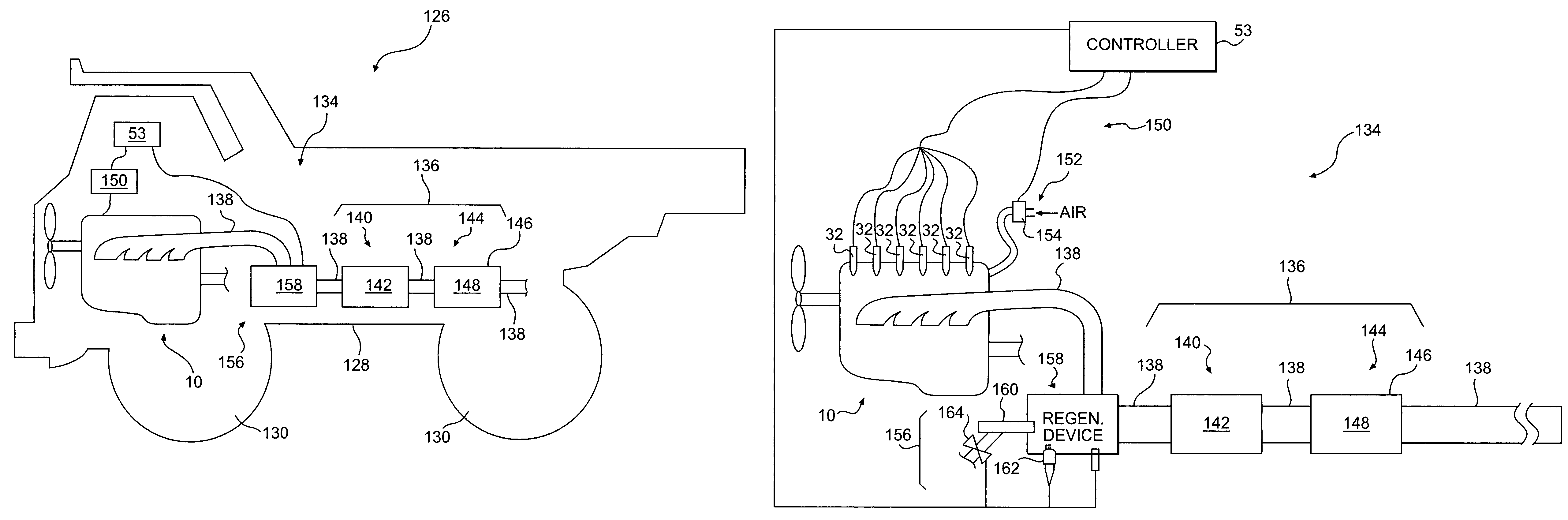
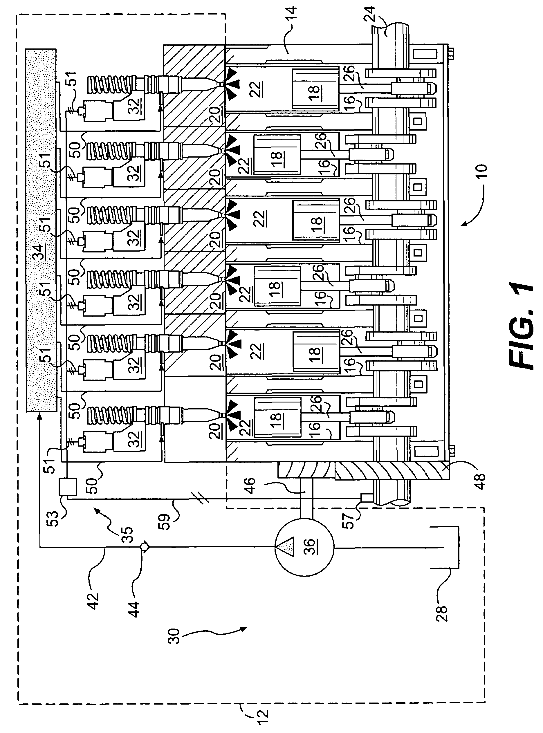
[0020]FIG. 1 illustrates an engine 10 and an exemplary embodiment of a fuel system 12. For the purposes of this disclosure, engine 10 is depicted and described as a four-stroke diesel engine. One skilled in the art will recognize, however, that engine 10 may be any other type of internal combustion engine such as, for example, a gasoline or a gaseous fuel-powered engine. Engine 10 may include an engine block 14 that defines a plurality of cylinders 16, a piston 18 slidably disposed within each cylinder 16, and a cylinder head 20 associated with each cylinder 16.

[0021]Cylinder 16, piston 18, and cylinder head 20 may form a combustion chamber 22. In the illustrated embodiment, engine 10 includes six combustion chambers 22. However, it is contemplated that engine 10 may include a greater or lesser number of com...


PUM


Abstract

A parasitic load control system is provided. The system may include an exhaust producing engine and a fuel pumping mechanism configured to pressurize fuel in a pressure chamber. The system may also include an injection valve configured to cause fuel pressure to build within the pressure chamber when in a first position and allow injection of fuel from the pressure chamber into one or more combustion chambers of the engine when in a second position. The system may further include a controller configured to independently regulate the pressure in the pressure chamber and the injection of fuel into the one or more combustion chambers, to increase a load on the fuel pumping mechanism, increasing parasitic load on the engine, thereby increasing a temperature of the exhaust produced by the engine.

Description

U.S. GOVERNMENT RIGHTS[0001]The embodiments disclosed in this application were made with government support under the terms of DOE Award No. DE-FC05-97OR22605 awarded by the Department of Energy. The government may have certain rights in the embodiments disclosed in this application.TECHNICAL FIELD[0002]The present disclosure is directed to a parasitic load control system and, more particularly, to a parasitic load control system for controlling engine exhaust temperature.BACKGROUND[0003]Engines, including diesel engines, gasoline engines, natural gas engines, and other engines known in the art, may exhaust a complex mixture of air pollutants. The air pollutants may be composed of both gaseous and solid material, such as, for example, particulate matter. Particulate matter may include ash and unburned carbon particles called soot.[0004]Due to increased environmental concerns, exhaust emission standards have become more stringent. The amount of particulate matter and gaseous pollutan...

Claims


Application Information

Patent Timeline
Patent Type & Authority Patents(United States)
IPC IPC(8): F01N3/00
CPCF01N3/0256F01N3/035F01N3/106F01N3/2033F01N3/206F02M45/02F02M47/027F02M57/023F02M59/366F01N13/0097F01N13/009F01N2240/14F02D41/029F02D41/3836F02D2041/026Y02T10/26Y02T10/12
Inventor STRAUSER, AARON D.COLEMAN, GERALD N.COLDREN, DANA R.
Owner CATERPILLAR INC
Why Eureka
Try Eureka