Plasma display panel
a technology of display panel and plasma, which is applied in the direction of discharge electrodes, discharge tubes luminescnet screens, gas-filled discharge tubes, etc., can solve the problems of increased manufacturing cost of pdp, high discharge firing voltage, and uneven discharge, so as to improve the electrode structure and enhance the emission luminance and discharge efficiency
- Summary
- Abstract
- Description
- Claims
- Application Information
AI Technical Summary
Benefits of technology
Problems solved by technology
Method used
Image
Examples
first embodiment
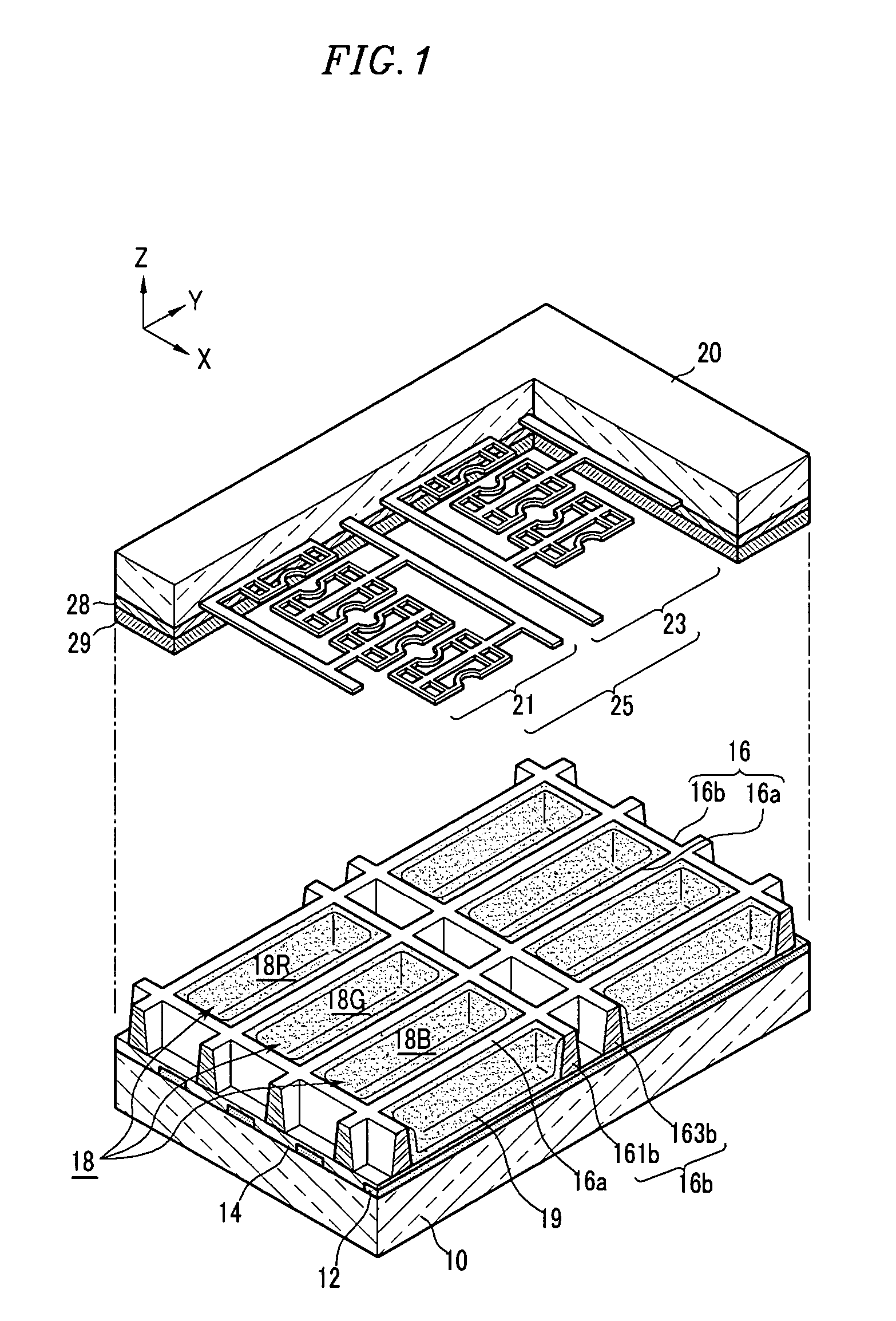
[0041]FIG. 1 is a partially exploded perspective view showing a plasma display panel according to the present invention.
[0042]Referring to FIG. 1, the plasma display panel (hereinafter, referred to as PDP) according to the present embodiment includes a front substrate 20 and a rear substrate 10 that is disposed to face the front substrate 20.
[0043]The front substrate 20 is made of a transparent material, such as glass, through which a visible light beam transmits to display an image.
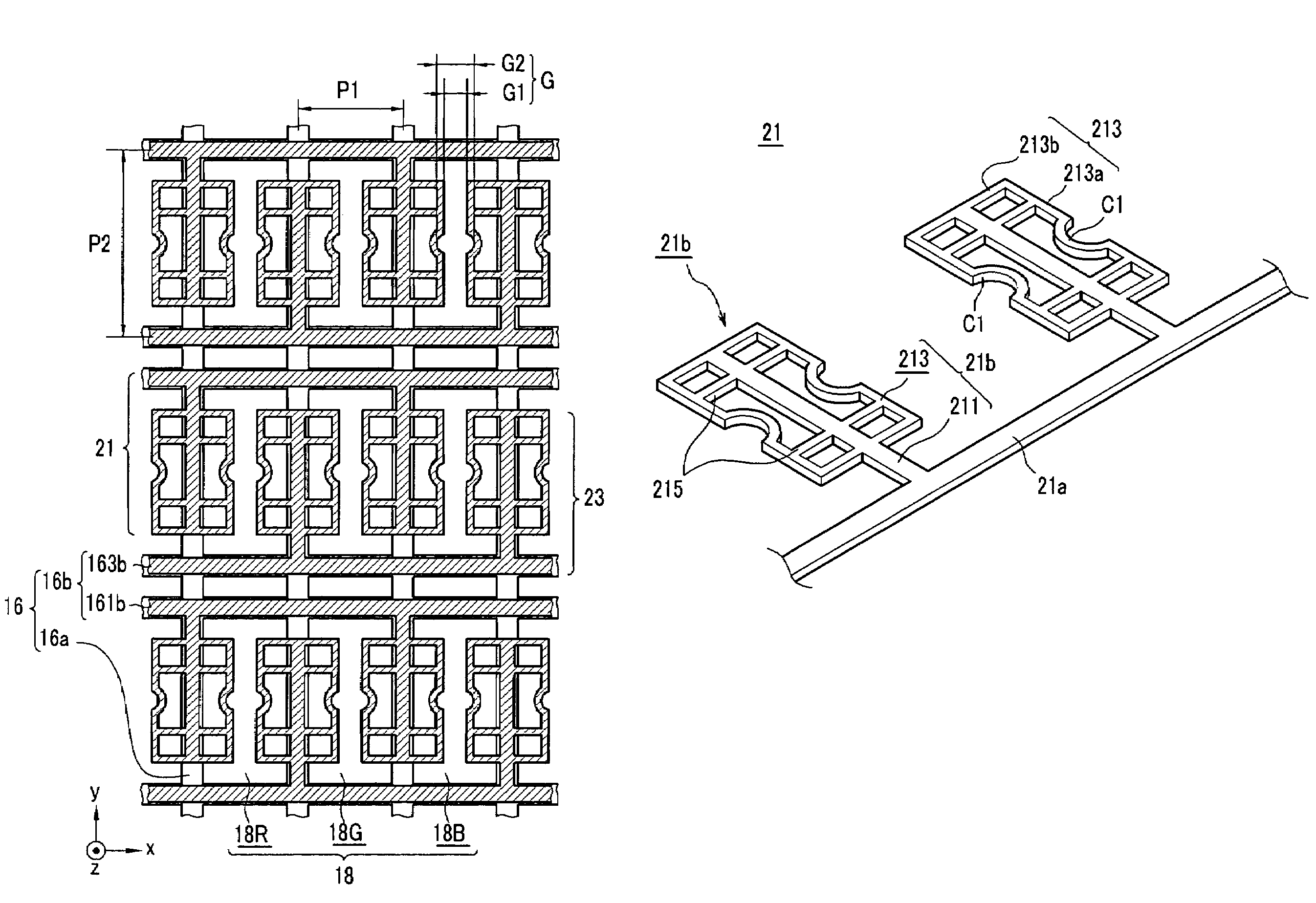
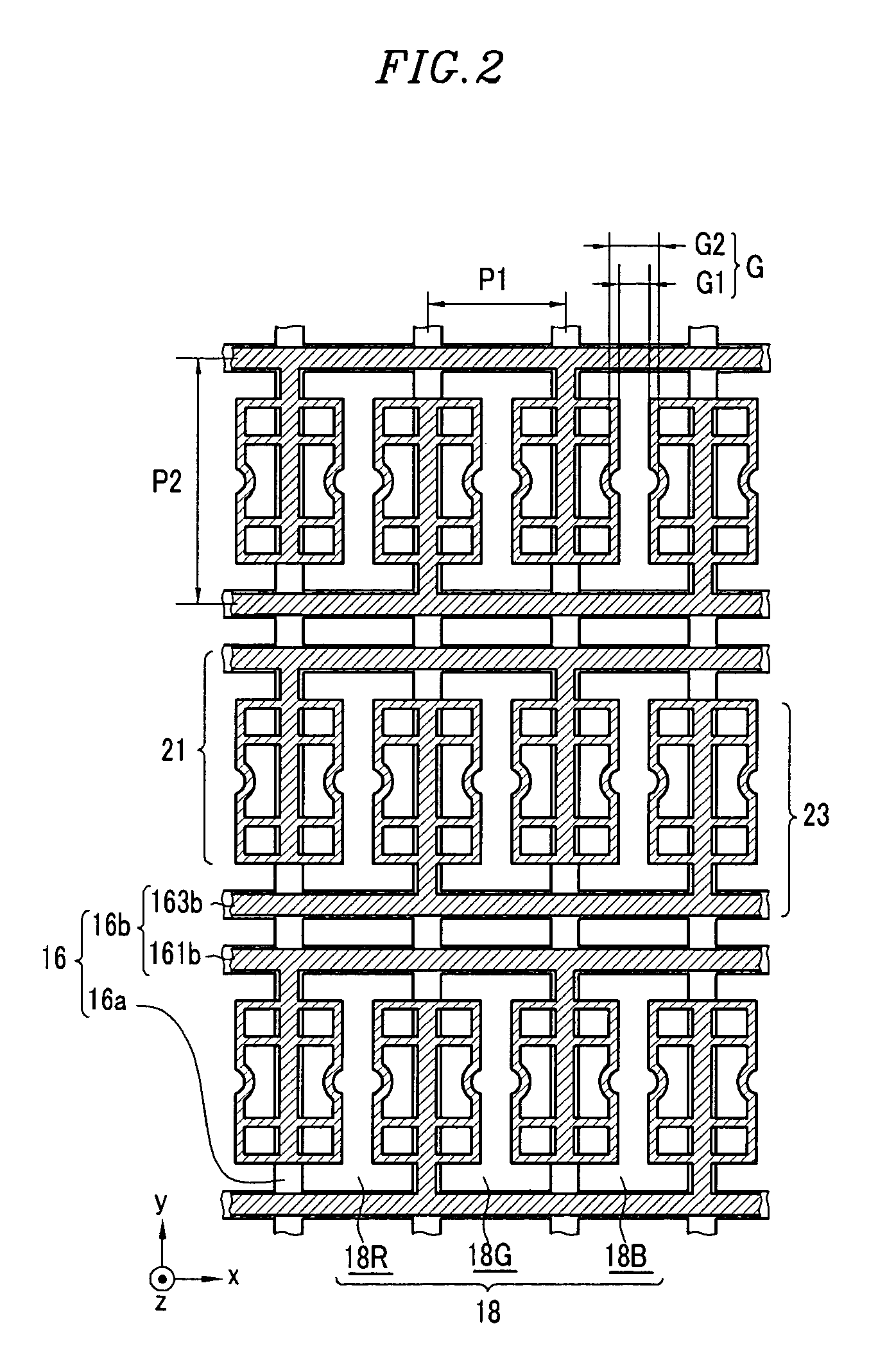
[0044]Display electrodes 25 are formed on the lower surface of the front substrate 20. In the present embodiment, the display electrodes 25 are geometrically formed in linear shapes in order to increase an aperture ratio of a discharge cell. The display electrodes 25 will be described below in more detail.
[0045]The display electrodes 25 may be covered and filled with a dielectric layer (or a first dielectric layer) 28 made of a dielectric material, such as PbO, B2O3, SiO2, or the like. The dielectric lay...
second embodiment
[0085]FIG. 7 is a plan view illustrating the positional relationship between display electrodes and barrier ribs according to the present invention.
[0086]A scan electrode 41 (having a linear portion 41a and a protruded portion 41b) and a sustain electrode 43 (having a linear portion 43a and a protruded portion 43b) of the second embodiment also have substantially the same configurations as described above, except that second concave portions C2 are formed in second electrode portions 413b and 433b, respectively.
[0087]The second concave portions C2 are in one embodiment connected to ends of first portions 411 and 431, respectively. Further, the second electrode portions 413b and 433b of second portions 413 and 433 may obliquely connect first electrode potions 413a and 433a of the second portions 413 and 433 to the first portions 411 and 431, respectively.
third embodiment
[0088]FIG. 8 is a plan view illustrating the positional relationship between display electrodes and barrier ribs according to the present invention.
[0089]The discharge cells 18 are divided into the red discharge cells 18R, the green discharge cells 18G, and the blue discharge cells 18B according to the colors represented by the phosphor layer coated on the respective discharge cells 18.
[0090]Also, as similar to the first and second embodiments described above, a scan electrode 61 and a sustain electrode 63 have linear portions 61a and 63a and protruded portions 61b and 63b, respectively. The protruded portions 61b and 63b are disposed in a pair of adjacent discharge cells on the respective vertical barrier ribs 16a.
[0091]In the third embodiment, in order to reduce the difference in luminance by colors of the discharge cells, the protruded portions 61b and 63b formed corresponding to the discharge cell for one color are formed to be larger than the protruded portions 63a and 63b dis...
PUM
 Abstract
Description
Claims
Application Information
 - R&D
- Intellectual Property
- Life Sciences
- Materials
- Tech Scout
- Unparalleled Data Quality
- Higher Quality Content
- 60% Fewer Hallucinations
Browse by: Latest US Patents, China's latest patents, Technical Efficacy Thesaurus, Application Domain, Technology Topic, Popular Technical Reports.
© 2025 PatSnap. All rights reserved.Legal|Privacy policy|Modern Slavery Act Transparency Statement|Sitemap|About US| Contact US: help@patsnap.com


