
X-ray source for materials analysis systems

a technology of x-ray source and materials analysis, applied in the field of radiation sources, can solve the problems of tube failure and radiation output degradation, and achieve the effects of reducing the power requirements of the x-ray source, rapid system turning on and off, and small size and mass

Inactive Publication Date: 2009-04-28
CARL ZEISS STIFTUNG DOING BUSINESS CARL ZEISS
View PDF33 Cites 37 Cited by
  • Summary
  • Abstract
  • Description
  • Claims
  • Application Information

AI Technical Summary

Benefits of technology

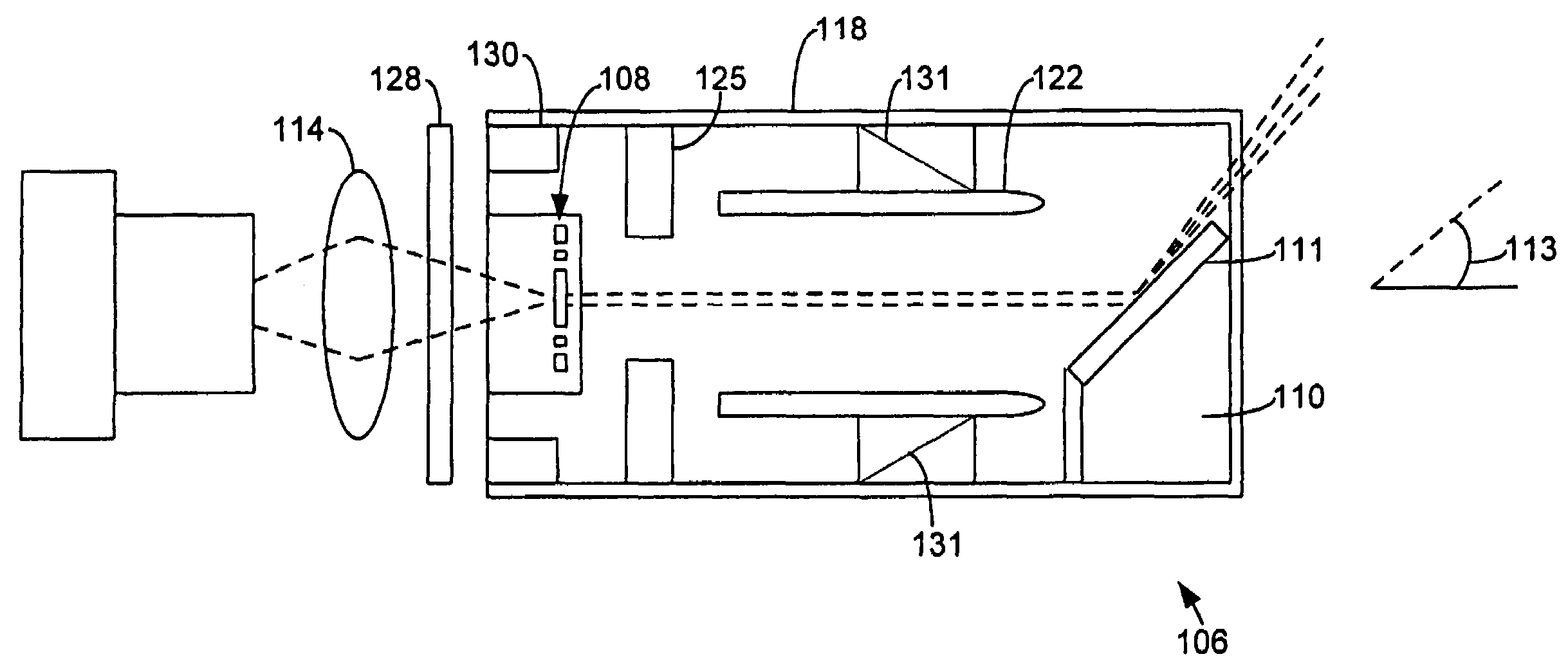
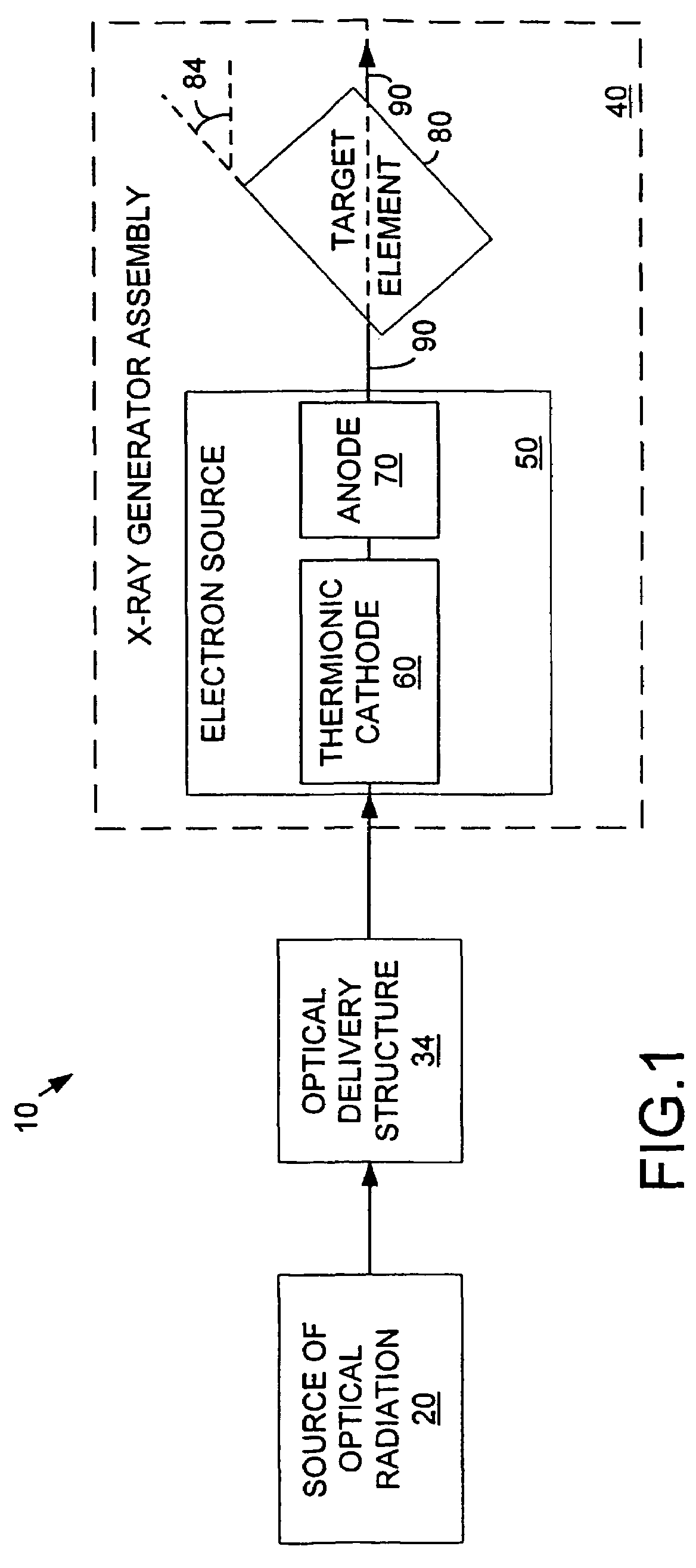
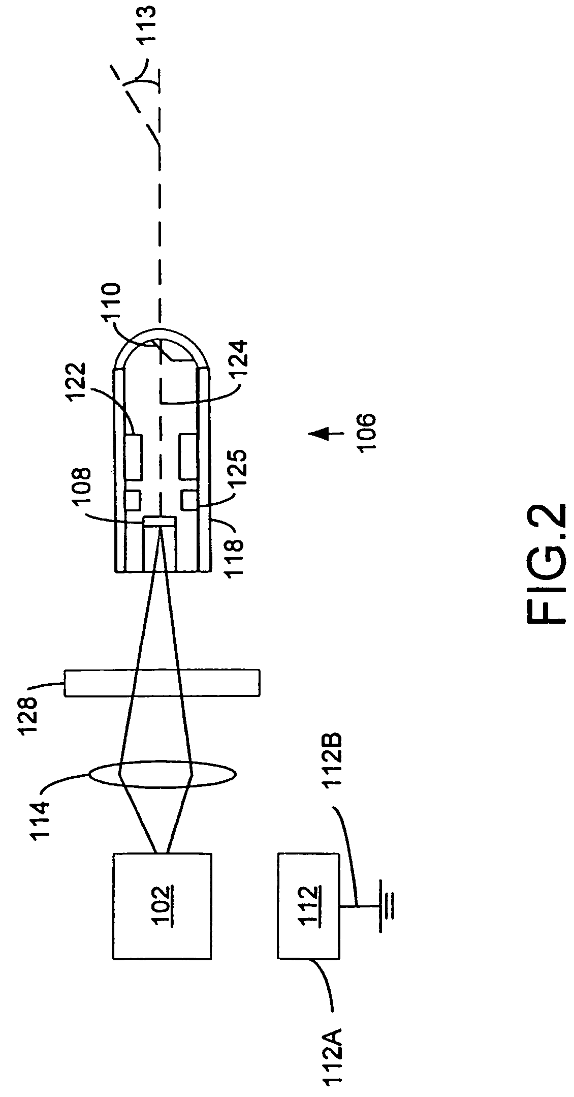
[0011]The x-ray generator assembly includes an electron source, an anode, and a target element. The electron source is responsive to optical radiation, generated by the optical source and transmitted through the optical delivery structure, to generate an electron beam along a beam path. The electron source is preferably a thermionic cathode having an electron emissive surface. The anode is positively biased relative to the thermionic cathode, and attracts the electrons emitted from the cathode. The target element is positioned in the electron beam path. The target element includes x-ray emissive material adapted to emit x-rays in response to incident accelerated electrons from the electron source. The anode intercepts and substantially eliminates leakage currents and field emitted currents. The accuracy of the target beam current measurement is thereby substantially increased.
[0014]In a preferred embodiment, the target element has an inclined surface defining an angle of inclination with respect to the beam path. The angle of inclination may be from about 40 degrees to about 50 degrees, and preferably is about 40 degrees. The target is preferably a grazing incidence target, i.e. a target from which x-rays are emitted substantially at or near the angle of the inclined plane. The grazing incidence target provides maximum target efficiency, at both high and low energies, and also provides maximum tunability of the x-ray source voltage.
[0016]Using a laser-heated thermionic cathode, rather than a resistively heated cathode, greatly reduces the power requirements for the x-ray source. In addition, the very small size and mass of the heated portion permits very rapid turning on and off of the system. This greatly reduces the average power consumption of the x-ray source. In one embodiment, the power required to heat the electron emissive surface of the cathode, so as to generate an electron beam forming a current of about 100 micro amps, was between about 0.1 Watts to about 3.0 Watts. Because of the greatly reduced power requirements, the x-ray source of the present invention can be fabricated in a miniaturized model, operating on portable battery power.

Problems solved by technology

In conventional x-ray tubes, for example, thermal vaporization of the tube's coiled cathode filament is frequently responsible for tube failure.
Also, the anode heated to a high temperature can cause degradation of the radiation output.

Method used


Image

  • X-ray source for materials analysis systems
  • X-ray source for materials analysis systems
  • X-ray source for materials analysis systems

Examples


Embodiment Construction

[0020]The present invention provides an optically driven, increased efficiency, miniaturized x-ray source for use in materials analysis systems. The x-ray source includes a laser-heated thermionic cathode, in contrast to prior art x-ray sources for materials analysis, which have resistively heated thermionic cathodes, or field emitter cathodes. Heating the thermionic cathode with a laser, rather than with a current, significantly reduces the power requirements for the x-ray source. The x-ray source includes an inclined-plane, grazing incidence target, by which the efficiency of x-ray generation may be improved.

[0021]FIG. 1 is a schematic block diagram of an overview of an x-ray source 10 for materials analysis, constructed according to the present invention. In overview, the x-ray source 10 includes an optical source 20, an optical delivery structure 30, and an x-ray generator assembly 40. The x-ray generator assembly 40 includes an electron source 50, an anode 70, and a target elem...


PUM


Abstract

A miniaturized, increased efficiency x-ray source for materials analysis includes a laser source, an optical delivery structure, a laser-driven thermionic cathode (108), an anode (122), and a target from the laser source and directs the beam onto a surface of the themionic cathode. The surfaces electrons form an electron beam along a beam path. The target element (110) is disposed in the beam path, and emits x-rays in response to incident accelerated electrons from the thermionic cathode. The target element includes an inclined surface that forms an angle of inclination (113) of about 40 degrees with respect to the electon beam path, so that x-rays are emitted from the target substantially at an angle of about 45 degrees with respect to the electron beam path.

Description

FIELD OF THE INVENTION[0001]The present invention relates to radiation sources, and more particularly to an increased efficiency, optically-driven, miniaturized x-ray source for materials analysis systems.BACKGROUND OF THE INVENTION[0002]X-rays are widely used in materials analysis systems. For example, x-ray spectrometry is an economical technique for quantitatively analyzing the elemental composition of samples. The irradiation of a sample by high energy electrons, protons, or photons ionizes some of atoms in the sample. These atoms emit characteristic x-rays, whose wavelengths depends on the atomic number of the atoms forming the sample, because x-ray photons typically come from the tightly bound inner-shell electrons in the atoms. The intensity of the emitted x-ray spectra is related to the concentration of the atoms within the sample.[0003]Another example is x-ray fluoroscopy, which is used for chemical analyses of solids and liquids. Typically, a specimen is irradiated by an i...

Claims


Application Information

Patent Timeline
Patent Type & Authority Patents(United States)
IPC IPC(8): H01J35/30H01J35/06H01J35/32
CPCH01J35/06H01J35/32H01J35/064
Inventor DINSMORE, MARK
Owner CARL ZEISS STIFTUNG DOING BUSINESS CARL ZEISS
Learn More