Lateral junction field-effect transistor
a field-effect transistor and junction technology, applied in transistors, semiconductor devices, electrical equipment, etc., can solve the problems of breakdown voltage performance deterioration, breakdown voltage performance degradation, etc., to achieve the effect of high resistance, easy to achieve, and high withstand voltag
- Summary
- Abstract
- Description
- Claims
- Application Information
AI Technical Summary
Benefits of technology
Problems solved by technology
Method used
Image
Examples
first embodiment
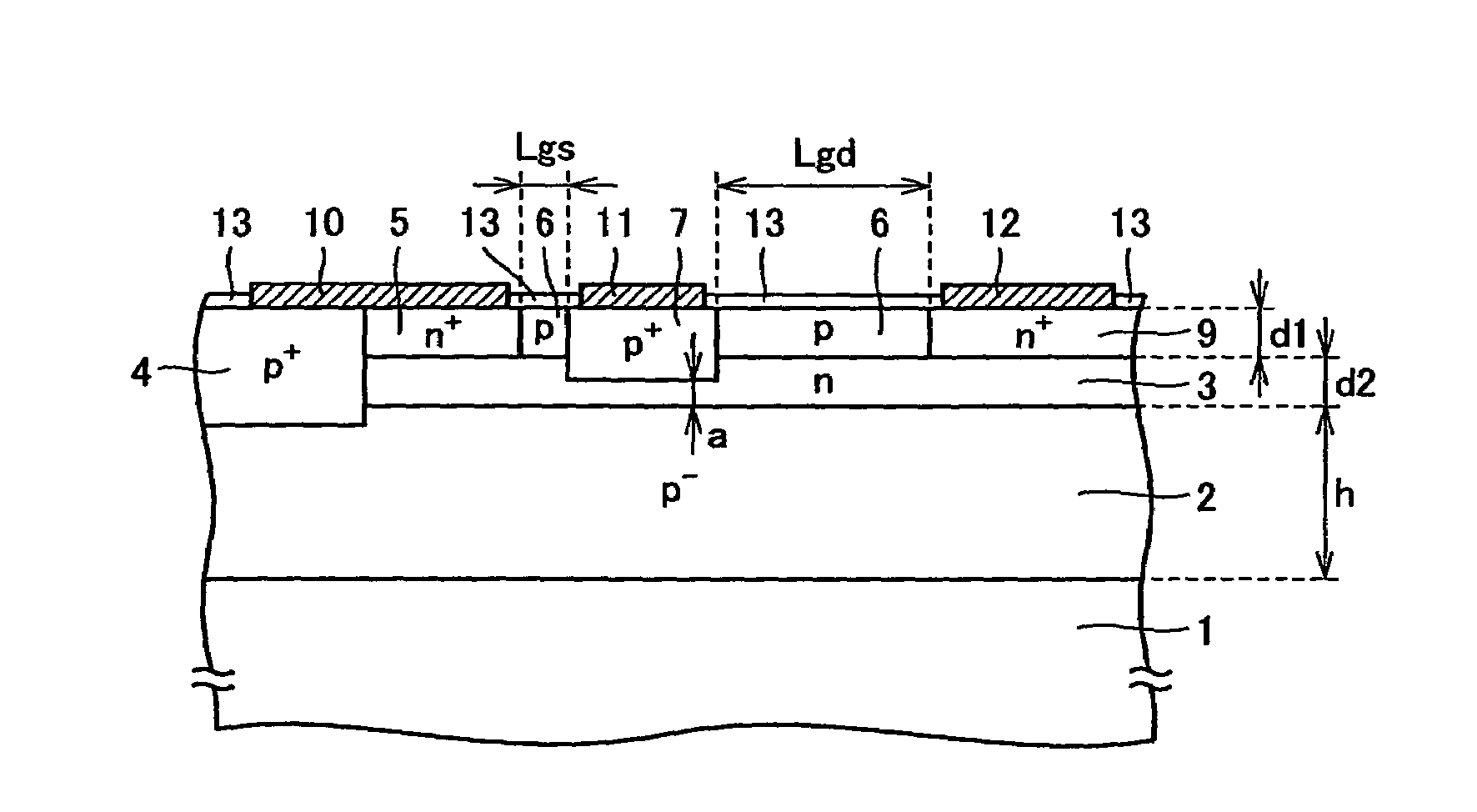
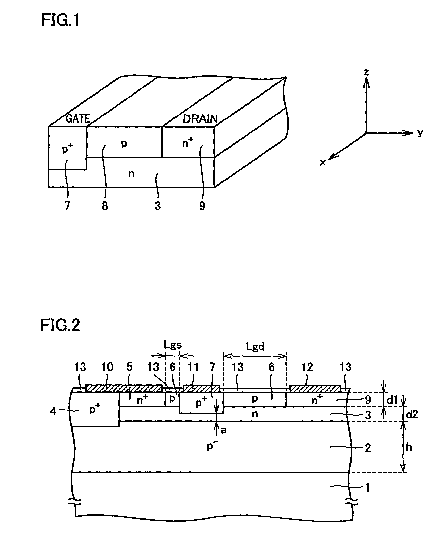
[0052]Referring to FIG. 2, a structure of a lateral JFET is described according to this embodiment. The semiconductor substrate used here is a single crystal SiC substrate of any conductivity type. On this single crystal SiC substrate 1, a p−-type epitaxial layer 2 which is a first semiconductor layer containing impurities of a first conductivity type is provided as shown in FIG. 2. On this p−-type epitaxial layer 2, an n-type epitaxial layer 3 is provided that is a second semiconductor layer containing impurities of a second conductivity type with a higher concentration than that of p−-type epitaxial layer 2. On this n-type epitaxial layer 3, a p-type epitaxial layer 6 is provided that is a third semiconductor layer.
[0053]In this p-type epitaxial layer 6, an n+-type source region layer 5 and an n+-type drain region layer 9 are provided at a predetermined distance therebetween that contain impurities of the second conductivity type with a higher concentration than. the impurity conc...
second embodiment
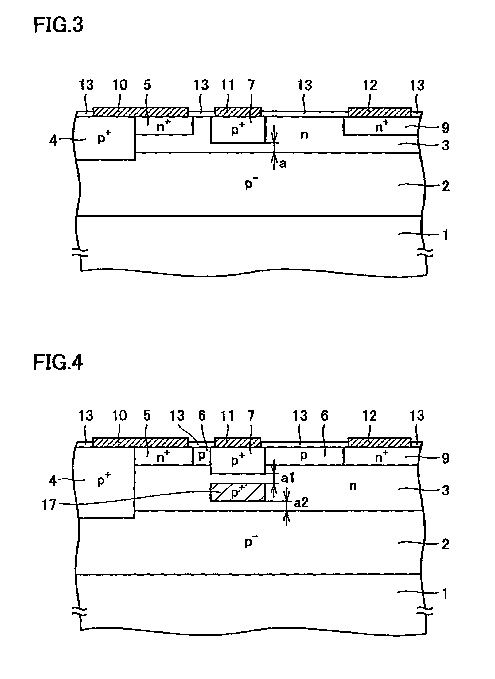
[0058]Referring to FIG. 3, a structure of a lateral JFET according to this embodiment is now described. The above-discussed lateral JFET of the first embodiment has p-type epitaxial layer 6 provided on n-type epitaxial layer 3 and n+-type source region layer 5, n+-type drain region layer 9 and p+-type gate region layer 7 are provided in this p-type epitaxial layer 6. According to the second embodiment, the lateral JFET does not include p-type epitaxial layer 6 on n-type epitaxial layer 3 and has its n+-type source region layer 5, n+-type drain region layer 9 and p+-type gate region layer 7 formed in n-type epitaxial layer 3. This structure is the same as that of the first embodiment except for the above-described details.
[0059]The structure as described above also provides an electric field distribution which is a constant electric field similar to that of parallel-plate capacitors, instead of the electric field distribution of the normal pn junction. Accordingly, a decreased ON res...
third embodiment
[0061]Referring to FIG. 4, a structure of a lateral JFET according to this embodiment is described. The lateral JFET of this embodiment has the same basic structure as that of the first embodiment, and one feature of the third embodiment is that one impurity injection region 17 is provided, in n-type epitaxial layer 3, between p−-type epitaxial layer 2 and p+-type gate region layer 7, and this region 17 has almost the same impurity concentration and the same potential as those of p+-type gate region layer 7.
[0062]This structure also provides an electric field distribution which is a constant electric field similar to that of parallel-plate capacitors, instead of the electric field distribution of the normal pn junction. Accordingly, a decreased ON resistance is achieved while the withstand voltage is maintained, as compared with the lateral JFET of the conventional structure.
[0063]Further, distance (a1) in this structure between the top of impurity injection region 17 and the bottom...
PUM
 Abstract
Description
Claims
Application Information
 - R&D
- Intellectual Property
- Life Sciences
- Materials
- Tech Scout
- Unparalleled Data Quality
- Higher Quality Content
- 60% Fewer Hallucinations
Browse by: Latest US Patents, China's latest patents, Technical Efficacy Thesaurus, Application Domain, Technology Topic, Popular Technical Reports.
© 2025 PatSnap. All rights reserved.Legal|Privacy policy|Modern Slavery Act Transparency Statement|Sitemap|About US| Contact US: help@patsnap.com


