Control device for supercharger with electric motor

a control device and supercharger technology, applied in the direction of electric generator control, electric control, machines/engines, etc., can solve the problems of reducing the supercharger efficiency (increase of back pressure), reducing the output, and reducing the air mass per unit volume, so as to reduce the intake air mass and reduce the output. , the effect of reducing the air mass

Inactive Publication Date: 2009-05-12
TOYOTA JIDOSHA KK
View PDF19 Cites 43 Cited by
  • Summary
  • Abstract
  • Description
  • Claims
  • Application Information

AI Technical Summary

Benefits of technology

[0004]The variable nozzle mechanism is a mechanism in which a plurality of vanes are disposed in an exhaust input part into a turbine wheel and which variably controls the exhaust flow rate by changing the gap between the vanes (variable nozzle opening). The turbine output is optimized by variably controlling the variable nozzle opening. However, the variable nozzle mechanism is already at the minimum opening when the internal combustion engine is in a low load region, and it is almost always the case that there is no space for increase in the boost pressure upon a decrease of the atmospheric pressure. If the nozzle opening is narrowed down too much, it will lead to a decrease of supercharging efficiency (increase of back pressure) as a turbocharger and, in turn, to reduction of fuel consumption. For this reason, there were desires for the output compensation in such cases. Therefore, an object of the present invention is to provide a control apparatus for an electrically assisted supercharger capable of effectively compensating for the decrease of the output even with decrease of the atmospheric pressure.

Problems solved by technology

For example, a decrease of the atmospheric pressure results in decreasing the air mass per unit volume and thus decreasing the output.
If the nozzle opening is narrowed down too much, it will lead to a decrease of supercharging efficiency (increase of back pressure) as a turbocharger and, in turn, to reduction of fuel consumption.

Method used


Image

  • Control device for supercharger with electric motor
  • Control device for supercharger with electric motor
  • Control device for supercharger with electric motor

Examples


Embodiment Construction

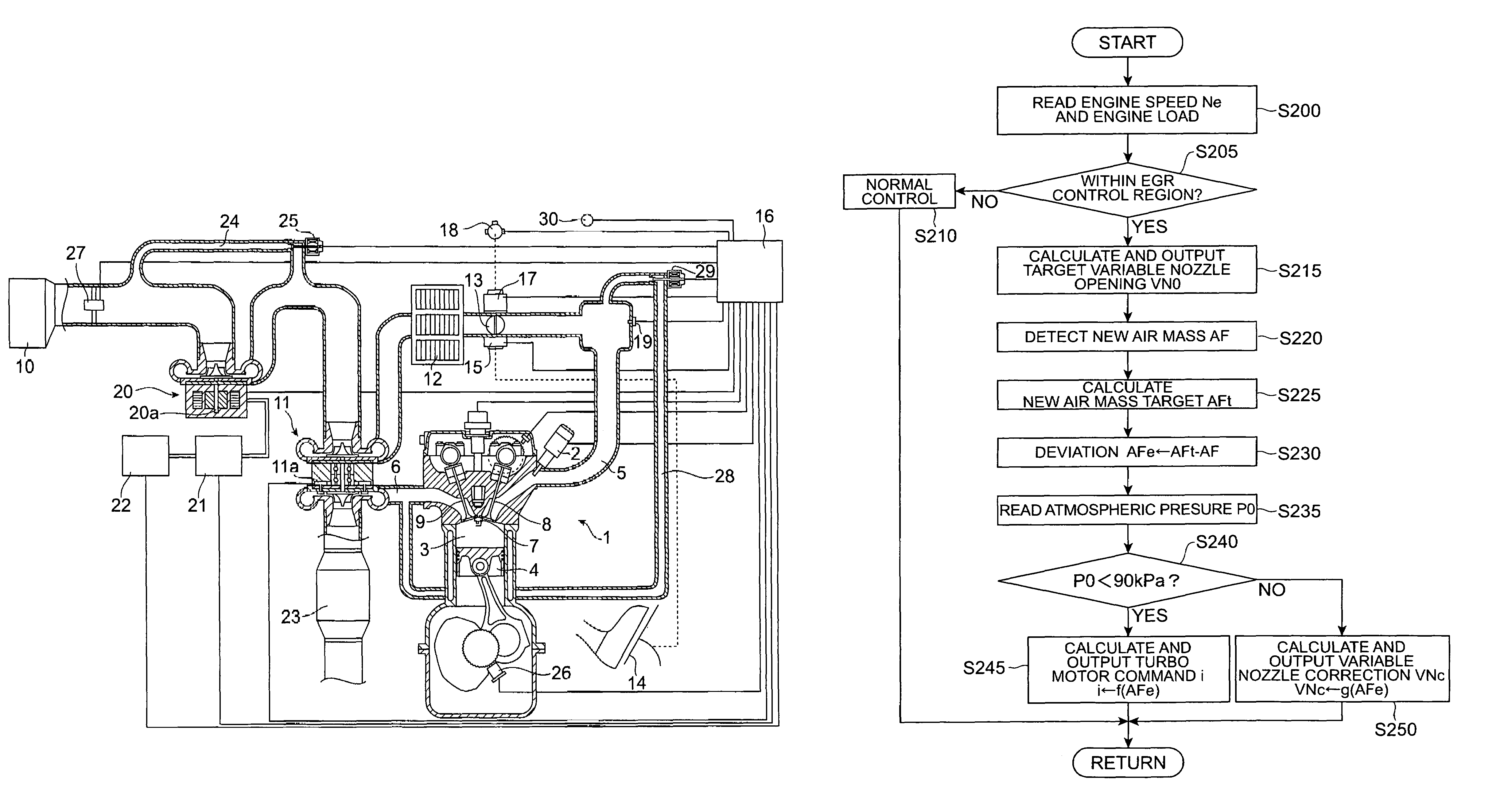
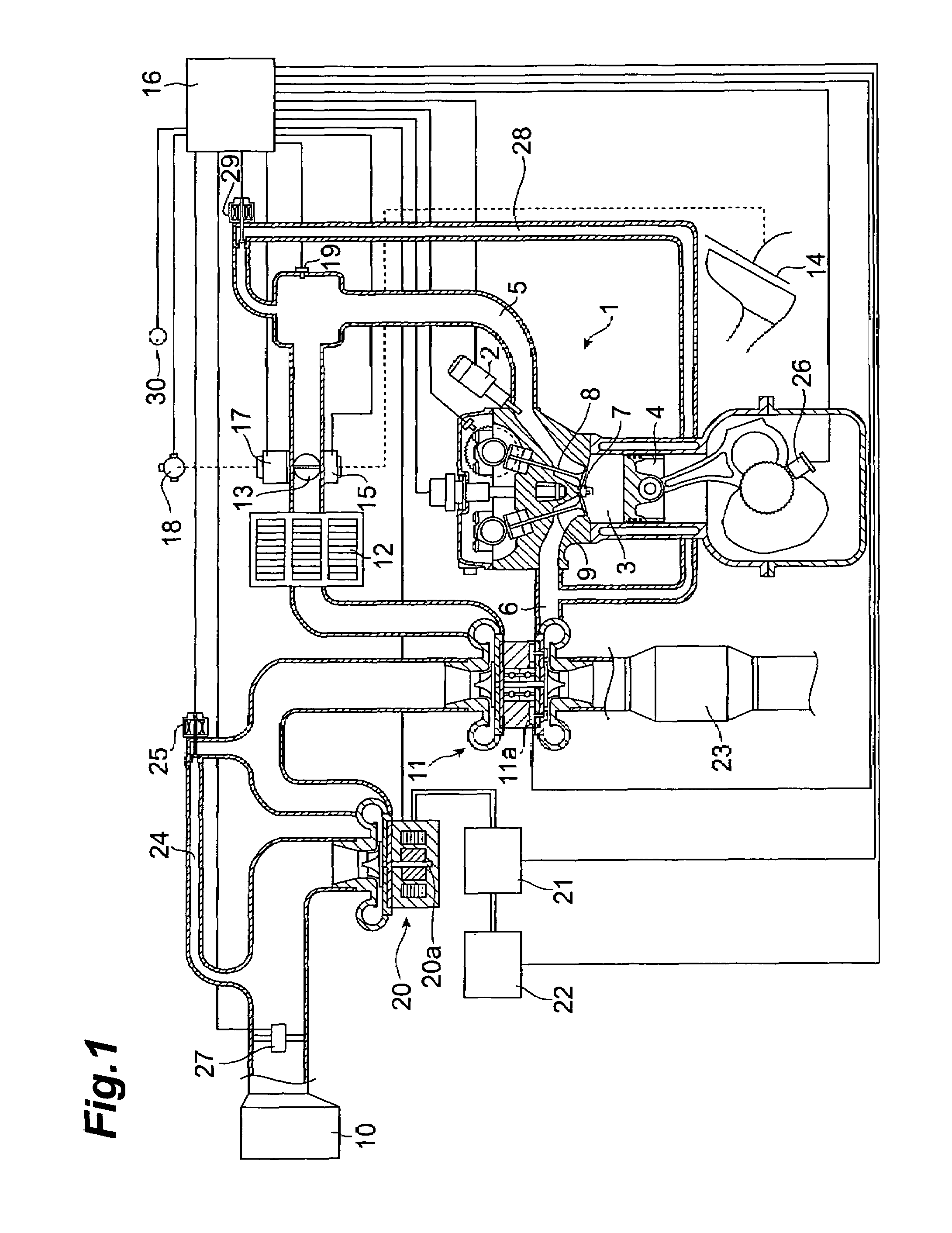
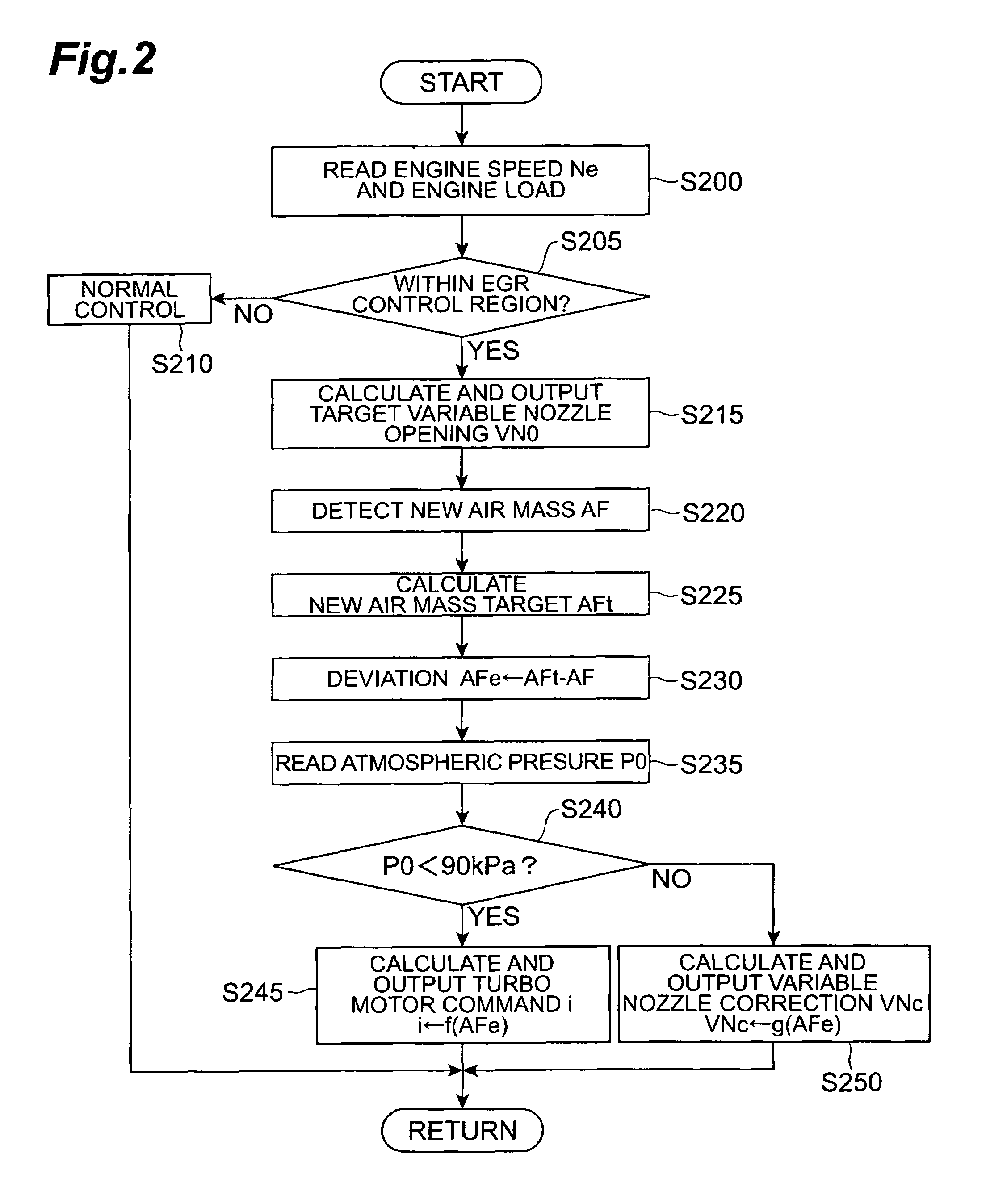
[0015]An embodiment of the control apparatus of the present invention will be described below. FIG. 1 shows engine 1 having the control apparatus of the present embodiment.

[0016]The term “boost pressure” is sometimes used as a term indicating a pressure difference from the atmospheric pressure. On the other hand, the term “boost pressure” is also sometimes used as a term indicating an absolute pressure in the intake pipe. If it is necessary to describe the boost pressure by definitely discriminating them, the description will be given so as to definitely indicate the meanings thereof. For example, when the boost pressure control is carried out based on an output of a pressure sensor for detecting the pressure in the intake pipe, it is easy to control the boost pressure, based on the “boost pressure as a difference from the atmospheric pressure,” if the pressure sensor is a sensor for detecting the differential pressure from the atmospheric pressure; it is easy to control the boost p...


PUM


Abstract

An object of the present invention is to provide a control apparatus for an electrically assisted supercharger capable of effectively compensating for an output drop even with decrease in the atmospheric pressure. A control apparatus for an electrically assisted supercharger according to the present invention has a supercharger 20 disposed on an intake passage 5 of an internal combustion engine 1 mounted on a vehicle, and driven by an electric motor 20a, a controller 16, 21 for controlling the electric motor 20a to control a boost pressure, and a pressure detector 30 for detecting a state of the atmospheric pressure, and is characterized in that when the atmospheric pressure detected by the pressure detector 30 becomes less than a predetermined value, the controller 16, 21 makes a driving force of the electric motor 20a larger than that when the atmospheric pressure is not less than the predetermined value.

Description

TECHNICAL FIELD[0001]The present invention relates to a control apparatus for an electrically assisted supercharger which controls the supercharger with an electric motor disposed on an intake passage of an internal combustion engine mounted on a vehicle.BACKGROUND ART[0002]There are well-known internal combustion engines provided with a turbocharger on the intake passage of the engine and configured to achieve high power (or low-fuel consumption) through supercharging by the turbocharger. Japanese Patent Application Laid-Open No. 11-132049 also discloses the internal combustion engine with the turbocharger.DISCLOSURE OF THE INVENTION[0003]An internal combustion engine takes in air from the atmosphere and uses it in combustion. The output reduces with decrease in the intake air mass. For example, a decrease of the atmospheric pressure results in decreasing the air mass per unit volume and thus decreasing the output. It is thus common practice to increase the throttle opening so as t...

Claims


Application Information

Patent Timeline
Patent Type & Authority Patents(United States)
IPC IPC(8): F02B33/44F02B37/12F02B37/14F02M25/07F02B33/00F02B37/04F02B37/10F02B37/24F02B39/10
CPCF02B37/22F02B37/24F02B39/10F02D41/18F02D41/0007Y02T10/121F02D2200/703Y02T10/144Y02T10/12
Inventor AKITA, KOICHI
Owner TOYOTA JIDOSHA KK
Why Eureka
Try Eureka