Supercharge Your Innovation With Domain-Expert AI Agents!

Horizontal vibratory centrifuge apparatus

a vibratory centrifuge and horizontal technology, applied in centrifuges, separation processes, filtration separation, etc., can solve the problems of reduced drying or dewatering, high cost of devices, and inefficient efficiency, and achieve maximum vibration

Active Publication Date: 2009-05-19
ELGIN POWER & SEPARATION SOLUTIONS LLC
View PDF15 Cites 1 Cited by
  • Summary
  • Abstract
  • Description
  • Claims
  • Application Information

AI Technical Summary

Benefits of technology

This approach enhances separation efficiency and reduces operational costs by achieving maximum vibration and separation between solid and liquid components using a low-energy motor in resonance with torsion springs, improving recovery and dewatering processes.

Problems solved by technology

However, the thick bed also reduces the drying or dewatering that occurs.
Such a device is very costly and inefficient.

Method used


Image

  • Horizontal vibratory centrifuge apparatus
  • Horizontal vibratory centrifuge apparatus
  • Horizontal vibratory centrifuge apparatus

Examples


Embodiment Construction

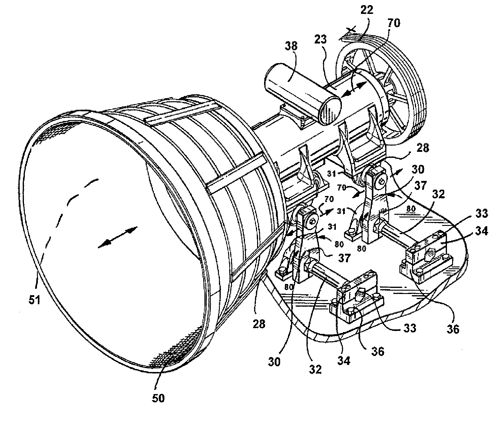
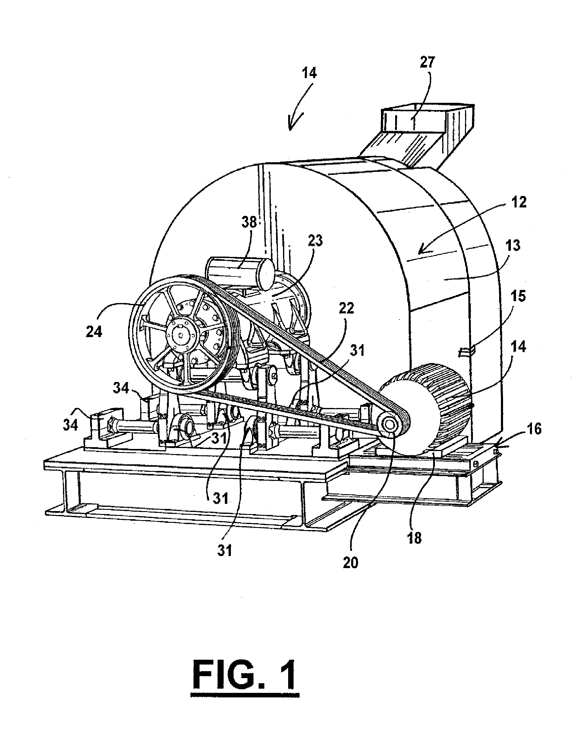
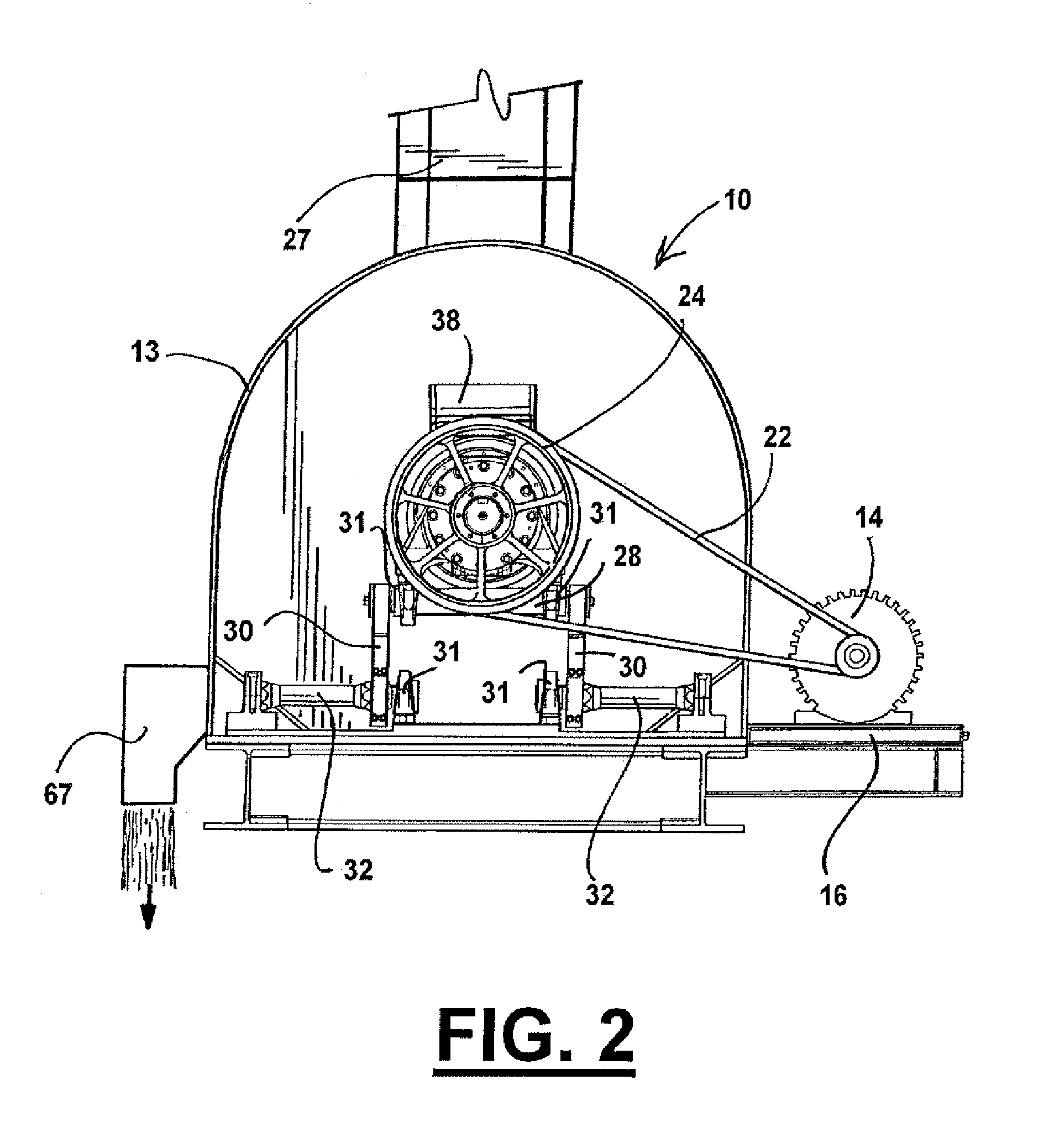
[0021]FIGS. 1-5 illustrate the preferred embodiment of the apparatus of the present invention by the numeral 10. As illustrated in the Figures, there is illustrated horizontal vibrating centrifuge apparatus 10 which includes a slurry separation component 12 having a circular outer wall 13, with a door latch 15, for having access to the rotating screen or basket 50 within the interior 51 of the separation component 12, through a rear wall 29. As seen in FIGS. 1 and 2, apparatus 10 includes an electrical drive motor 14, positioned on an adjustable motor base 16, held in position by motor mount 18. Drive motor 14 includes a drive motor sheave 20 through which a drive belt 22 is mounted to the drive assembly 23, upon which there is mounted a drive unit sheave 24 for accommodating the belt 22. Rotation of the belt 22 imparts rotation to the drive assembly 23 and ultimately the basket or rotating screen 50 within the interior 51 of the separation component 12. It should be noted that ther...


PUM

PropertyMeasurementUnit
mechanicalaaaaaaaaaa
magneticaaaaaaaaaa
frequencyaaaaaaaaaa

Abstract

A horizontal vibratory centrifuge, which includes a slurry separating component; a drive motor; a drive unit for rotating the separating component; a feed pipe for feeding the slurry into the separating component; a product discharge for discharging the solid portion of the slurry from the separating component and a pipe for discharging the fluid portion from the separating component; at least one vibratory motor mounted onto the drive unit; a plurality of connecting rods moveably connecting the drive unit to a torsion bar assembly, the assembly including a plurality of torsion bars, each mounted on a first end to an upper fixed spring clamp and a lower fixed spring clamp, and on a second end to the connecting rods with bearings, so that the vibrations of the low energy vibrating motor is in resonance with the springs so as to provide in part maximum vibration to the vibrating assembly at low energy levels. There is also provided the method of imparting vibration to a slurry in the separation component by a single low energy vibrating motor which operates in resonance with the torsion springs to achieve maximum vibration and thus maximum separation between the solid and liquid components of the slurry.

Description

CROSS-REFERENCE TO RELATED APPLICATIONS[0001]Not applicableSTATEMENT REGARDING FEDERALLY SPONSORED RESEARCH OR DEVELOPMENT[0002]Not applicableREFERENCE TO A “MICROFICHE APPENDIX”[0003]Not applicableBACKGROUND OF THE INVENTION[0004]1. Field of the Invention[0005]The apparatus of the present invention relates to vibratory centrifuges. More particularly, the present invention relates to an improved vibratory centrifuge which provides maximum vibration of the centrifuge through the natural resonance between a single vibratory motor and torsion springs upon which the system is mounted.[0006]2. General Background of the Invention[0007]Centrifugal separators or centrifuges such as horizontal centrifuges are generally used for the separation or the removal of liquid from solids such as coal or other types of solids. The vibratory centrifuge is usually defined as a low G machine that conveys solids over a screen surface with oscillating or vibratory motion. The machine is best suited for a r...

Claims


Application Information

Patent Timeline
Patent Type & Authority Patents(United States)
IPC IPC(8): B04B3/06
CPCB04B3/06B04B9/00B04B9/08B04B9/12
Inventor WHISLER, KEVIN R.BERTOCCHINI, CHRISTOPHER A.
Owner ELGIN POWER & SEPARATION SOLUTIONS LLC
Features
  • R&D
  • Intellectual Property
  • Life Sciences
  • Materials
  • Tech Scout
  • Unparalleled Data Quality
  • Higher Quality Content
  • 60% Fewer Hallucinations
Learn More