Brushless electric motor and instrument for a medical apparatus

a technology of electric motor and instrument, applied in the direction of electrical apparatus, dynamo-electric machines, synchronous machines, etc., can solve the problems of inefficient electric motor and coil apparatus drive, inability to accurately match the position of control magnets, and corrupt the sensor values of electromagnetic transducer elements, etc., to achieve efficient drive, small physical structure, and high exactness

Inactive Publication Date: 2009-05-19
W&H DENTALWERK
View PDF19 Cites 11 Cited by
  • Summary
  • Abstract
  • Description
  • Claims
  • Application Information

AI Technical Summary

Benefits of technology

[0035]The invention also relates to an instrument for a medical, in particular a dental, apparatus, which is equipped with a brushless electric motor such as that described above. An instrument such as this is preferably a hand piece or an angled piece for dental tools such that the advantages are particularly clearly applicable to this use of a brushless electric motor, specifically high exactness, efficient drive, small physical structure, high motor effectiveness, high torques and, in particular, high rotation speeds.
[0036]The small structure and the lack of a possibly provided control magnet and the associated attachment apparatus, in particular, allow further miniaturization and allow the hand piece to be more ergonomic, thus avoiding rapid fatigue in the hand of the operator, for example of a dentist, which is of major importance, particularly in the dental field, in which very exact work must be carried out.
[0037]The electric motor described above thus immensely simplifies the integration of the motor, in particular in dental hand pieces and angled pieces.

Problems solved by technology

However, brushless electric motors such as these have the disadvantage that the position of the control magnet must be matched extremely exactly to the position of the rotor magnet.
Furthermore, it is necessary to prevent rotation of the control magnet with respect to the rotor magnet before and during operation of the electric motor or during maintenance work, etc, since this would lead to incorrect information with respect to the position of the rotor magnet and of the corresponding rotating field, and would result in the electric motor and the coil apparatus being driven inefficiently.
Furthermore, there is always a risk during operation of the electric motor of the control magnet and rotor magnet rotating with respect to one another, which would once again corrupt the sensor values from the electromagnetic transducer elements.
Furthermore, the production of a control magnet such as this is highly costly, and the control magnets are relatively sensitive, which is further exacerbated by the fact that the control magnets should be kept as small as possible owing to the miniaturization requirements.
For this reason they are frequently brittle and can break not only during installation and adjustment but also during operation, thus resulting in the risk of fragments which damage or destroy other parts of the motor.

Method used


Image

  • Brushless electric motor and instrument for a medical apparatus
  • Brushless electric motor and instrument for a medical apparatus
  • Brushless electric motor and instrument for a medical apparatus

Examples


Embodiment Construction

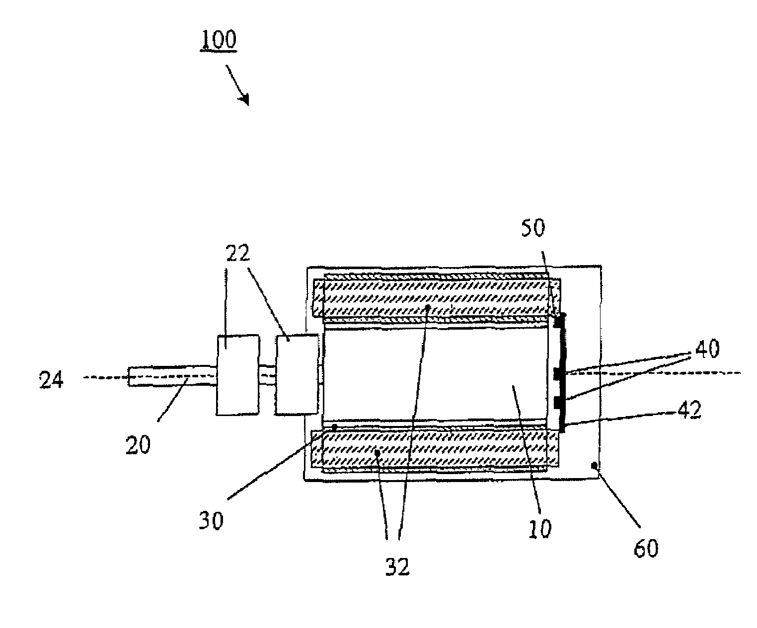
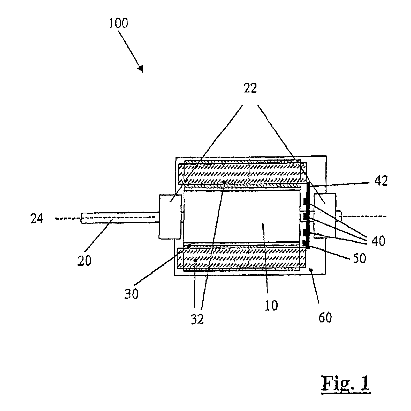
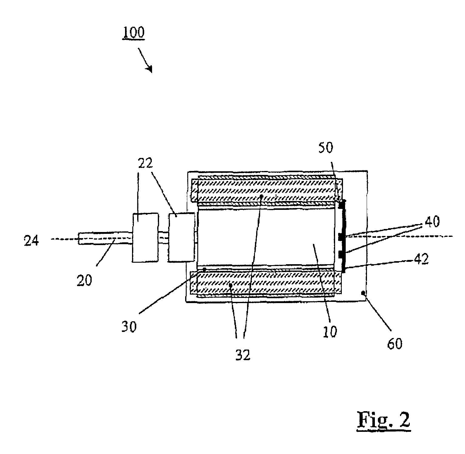
[0042]FIG. 1 shows, schematically, a first embodiment of a brushless electric motor according to the invention, with a main or rotor magnet 10, which is driven by means of schematically indicated stator windings 32 on a stator 30.

[0043]The rotor magnet 10 is a 2-pole magnet, whose individual poles each cover an angular range of about 180° in a section plane through the essentially cylindrical rotor magnet 10 running at right angles to a rotation axis 24 of the rotor magnet.

[0044]The rotor magnet 10 is firmly connected to a shaft 20, which transmits the rotary movement (which is produced by the stator windings 32 of the stator 30, which are used as a coil apparatus) to moving elements or tools, in particular dental tools such as a drill. The power can be transmitted to the dental tools in various ways, for example directly via gear wheels or in general via a transmission, in which case it is also possible to provide a clutch.

[0045]The shaft 20 is held by two bearings 22 such that it ...


PUM


Abstract

A brushless electric motor which has a rotor magnet, a coil apparatus for electromagnetically driving the rotor magnet, a rotor shaft for transmitting a rotary movement, which is firmly connected to the rotor magnet and runs through a rotation axis of the rotor magnet, and at least one electromagnetic transducer element for detection of the magnetic field of the rotor magnet, in which the at least one electromagnetic transducer element is arranged outside the axial extent of the rotor magnet with respect to the rotation axis, and is arranged essentially within the maximum radial extent of the rotor magnet. The invention also relates to an instrument for a medical, in particular a dental, apparatus having a brushless electric motor such as this.

Description

[0001]This application is a continuation of International Patent Application PCT / EP02 / 14422, filed on Dec. 17, 2002 and published on Jun. 26, 2003 under publication number WO 03 / 052906 A3 and claims priority benefits of German Application No. DE 101 61 945.6, filed Dec. 17, 2001.BACKGROUND OF THE INVENTION[0002]The present invention relates to a brushless electric motor which has a rotor magnet, a coil apparatus for electromagnetically driving the rotor magnet and a rotor shaft for transmitting a rotary movement to an element or an apparatus which can be moved. The rotor shaft being firmly connected to the rotor magnet and runs through a rotation axis of the rotor magnet. There is at least one electromagnetic transducer element for detection of the magnetic field of the rotor magnet.[0003]Electric motors such as these are available in various sizes and versions, are used in particular in handheld appliances, in particular medical and especially dental handheld appliances. The motors...

Claims


Application Information

Patent Timeline
Patent Type & Authority Patents(United States)
IPC IPC(8): H02K11/04H02K29/08
CPCH02K29/08
Inventor KARDEIS, RICHARDSEVCIK, ROLANDEIBL, JOHANNSCHROCK, RAINERSCHORGHOFER, HARALDMACKINGER, RAINERWENDTNER, WOLFGANGKOBEL, DIETER
Owner W&H DENTALWERK
Why Eureka
Try Eureka