Battery pack

a battery pack and battery charger technology, applied in the field of batteries, can solve the problems of reducing the capacity of the battery set, affecting the service life of the battery pack, and the entire battery pack becoming unusable, so as to achieve the effect of only reducing the capacity

Inactive Publication Date: 2009-05-19
PANASONIC CORP
View PDF7 Cites 47 Cited by
  • Summary
  • Abstract
  • Description
  • Claims
  • Application Information

AI Technical Summary

Benefits of technology

[0011]It is an object of the present invention to provide a battery pack which can be kept in use, by specifying an abnormal secondary-battery cell and separating a series module including this secondary-battery cell, with this single series module's capacity only reduced.

Problems solved by technology

Thereby, the capacity of this parallel battery (i.e., the latter secondary-battery cell connected in parallel) is reduced, resulting in a drop in the battery set's capacity.
When an abnormality is detected in charging this battery set, both an overcharge abnormality in a battery pack's parallel modules and an abnormality in a battery charger can be detected.
However, in the abnormality detection apparatus according to the prior art, an abnormality in the battery pack can be detected, but if a failure is produced in only one secondary-battery cell, the entire battery pack becomes unusable.

Method used


Image

  • Battery pack
  • Battery pack
  • Battery pack

Examples


first embodiment

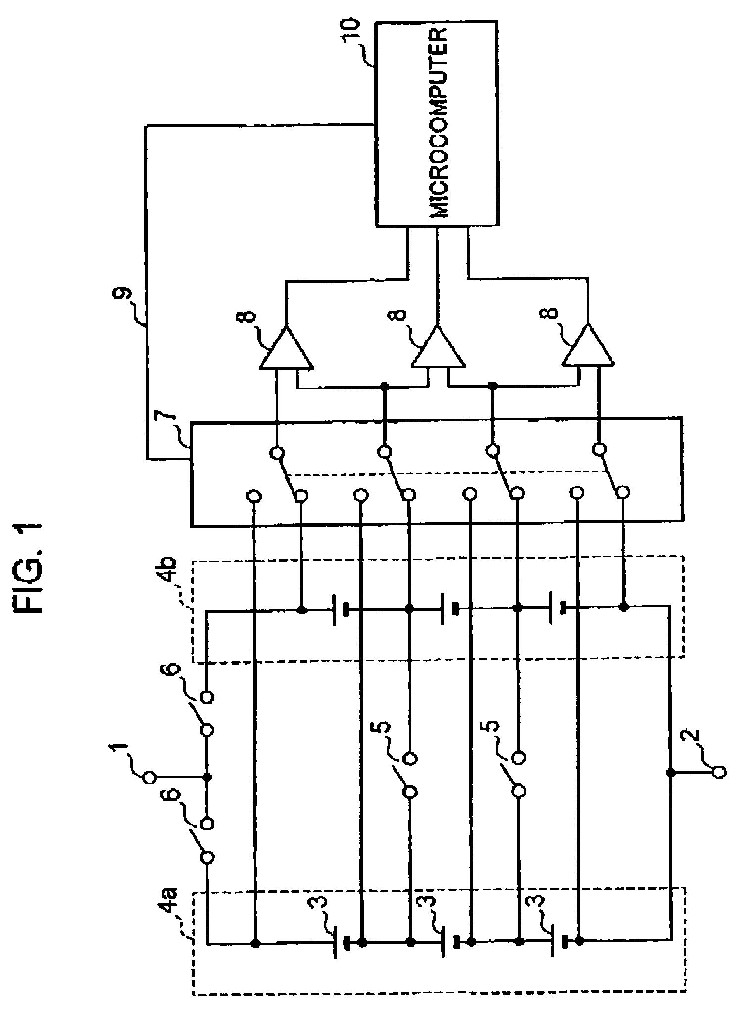
[0023]FIG. 1 is a circuit diagram, typifying the circuit configuration of a battery pack according to a first embodiment of the present invention. In this case, the number of series modules in parallel is two.

[0024]In FIG. 1, reference numeral 1 denotes a plus terminal and reference numeral 2 designates a minus terminal. The plus terminal 1 and the minus terminal 2 are connected to an external circuit (not shown) as the external load. Three secondary-battery cells 3 are connected in series to form each series module 4a, 4b. The two series modules 4a, 4b are connected in parallel between the plus terminal 1 and the minus terminal 2. Thereby, a battery set is formed.

[0025]In addition, the secondary-battery cells 3 which make up the series modules 4a, 4b are each connected in parallel via a parallel-connection separation switch 5. Besides, a battery-set circuit separation switch 6 is connected to each series module 4a, 4b. Thereby, each series module 4a, 4b can be separated from a batt...

second embodiment

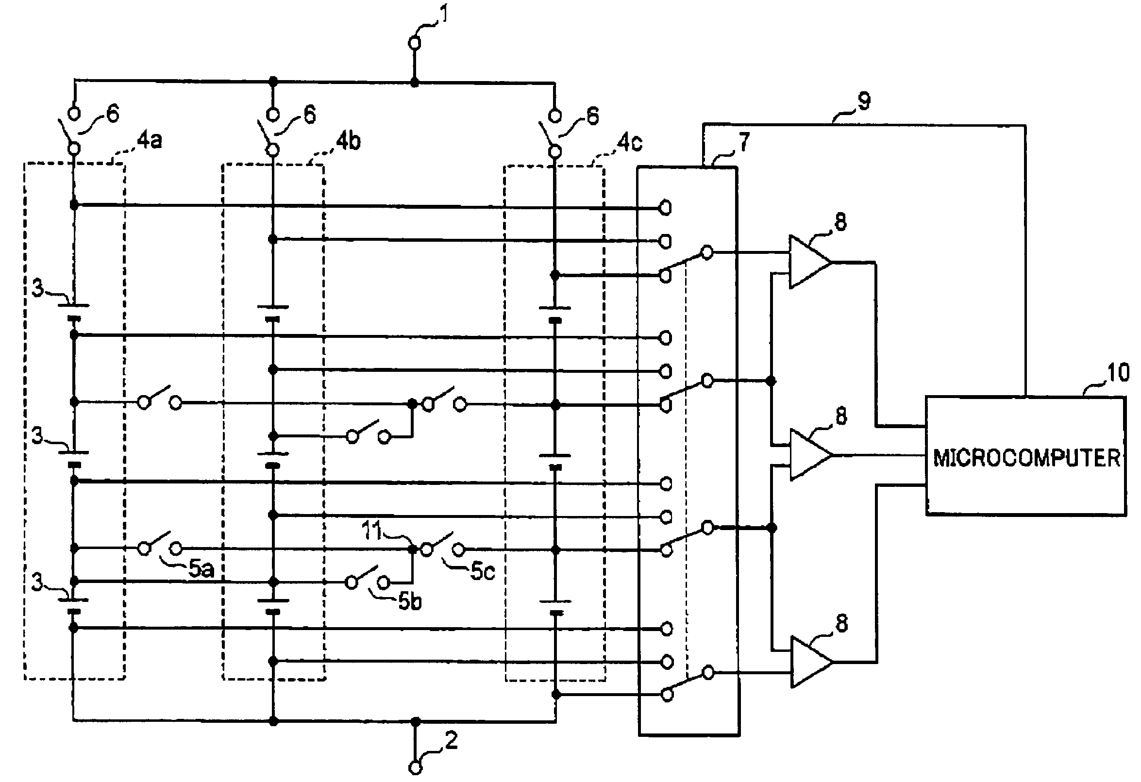
[0034]FIG. 2 is a circuit diagram, typifying the circuit configuration of a battery pack according to a second embodiment of the present invention. In this case, the number of series modules in parallel is three.

[0035]Herein, component elements are given the same reference characters and numerals as those of FIG. 1, as long as they each have an equivalent function to those according to the first embodiment described earlier. Thus, their description is omitted. The method of monitoring the voltage at the time of an ordinary operation and measuring the voltage of the individual secondary-battery cells 3 at regular intervals is identical to that of the first embodiment

[0036]This embodiment is different from the first embodiment, in the connection relation between three series modules 4a, 4b, 4c and three parallel-connection separation switches 5a, 5b, 5c. FIG. 3 is an illustration, typifying the connection relation between the series modules and the parallel-connection separation switc...

third embodiment

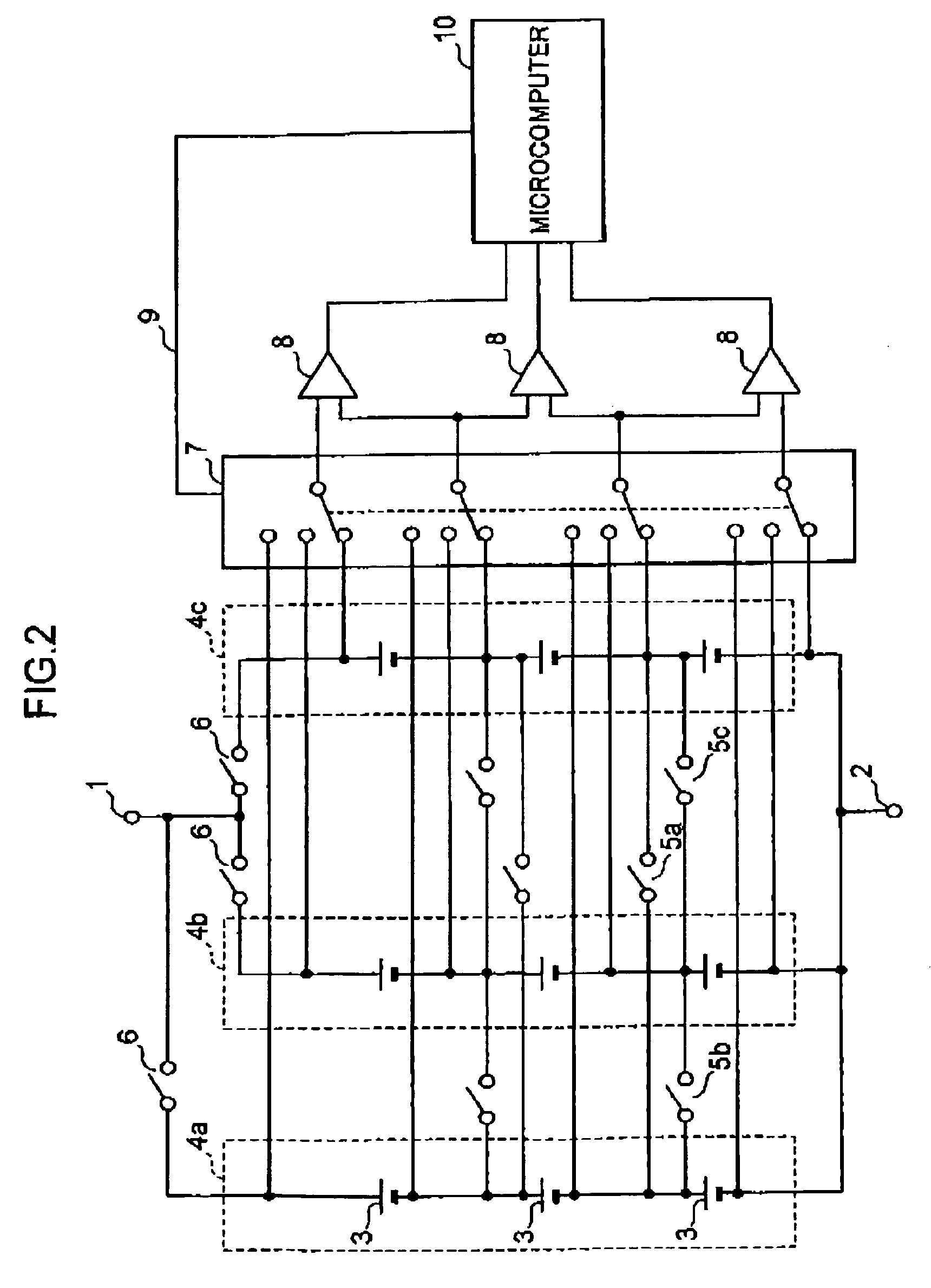
[0039]As described so far, in the first embodiment or the second embodiment, individual secondary-battery cells are directly connected via parallel-connection separation switches. In this connection method, their circuit can be easily formed in the case of two or three series modules. However, if more series modules are provided, they are difficult to connect in a network form. Hence, according to a third embodiment of the present invention, this problem can be resolved in the following way.

[0040]FIG. 4 is a circuit diagram, typifying the circuit configuration of a battery pack according to the third embodiment. In this case as well, the number of series modules in parallel is three.

[0041]Herein, component elements are given the same reference characters and numerals as those of FIG. 1, as long as they each have an equivalent function to those according to the first embodiment described earlier. Thus, their description is omitted. The method of monitoring the voltage at the time of ...


PUM


Abstract

A battery pack is provided which includes: a battery set having a plurality of secondary-battery cells connected in series and in parallel; and a battery-abnormality detection circuit. The battery-abnormality detection circuit controls a battery-set circuit separation switch, so as to detect an abnormality in each secondary-battery cell based on a change in the voltage of each cell when parallel-connection separation switches are turned off, and if detecting an abnormal secondary-battery cell, so as to separate the series module including this cell from a battery-set body.

Description

BACKGROUND OF THE INVENTION[0001]1. Field of the Invention[0002]The present invention relates to a battery pack which is formed by using secondary-battery cells that are repeatedly charged and discharged. Particularly, it relates to a battery pack which includes a battery-abnormality detection circuit for detecting a secondary-battery cell being abnormal.[0003]2. Description of the Background Art[0004]A battery pack is used as the power source of electronic equipment, such as a cellular phone and a notebook personal computer. A nickel-cadmium battery, a nickel-metal hydride battery or a lithium-ion secondary battery is used for a battery pack. In recent years, a lithium-ion secondary battery is most popular because of its light weight and large capacity.[0005]Herein, if the voltage or the capacity of a single lithium-ion secondary battery is enough for the power required for a mobile phone or the like, a battery pack is formed by one lithium-ion secondary battery. On the other hand,...

Claims


Application Information

Patent Timeline
Patent Type & Authority Patents(United States)
IPC IPC(8): H02J7/00H02J7/02H02J7/34
CPCH02J7/0026H02J7/0014H02J7/0029H02J7/0048Y02E60/10H01M10/425H02J7/0068H01M50/20H01M2010/4271
Inventor KIMURA, TADAOMORIMOTO, NAOHISAKURANAKA, SO
Owner PANASONIC CORP
Why Eureka
Try Eureka