Cam tube bracket

a technology of cam tube and cam tube bracket, which is applied in the direction of couplings, mechanical equipment, transportation and packaging, etc., can solve the problems of cam shaft impact load, cam shaft experience, cam shaft movement, etc., to increase the resistance to cam tube movement, reduce fretting, and increase load capacity

Active Publication Date: 2009-05-26
HENDRICKSON USA L L C
View PDF19 Cites 34 Cited by
  • Summary
  • Abstract
  • Description
  • Claims
  • Application Information

AI Technical Summary

Benefits of technology

[0014]An objective of the present invention is to provide an improved cam tube bracket which increases resistance to cam tube movement induced by loads placed on the axle / suspension system during operation of the vehicle, as well as from loads caused by operation of the brake system, and increases load capacity of the cam shaft support / enclosure assembly, resulting in reduced fretting at the cam tube-bracket interface, so that the cam tube is more securely attached
[0015]Still another objective of the present invention is to provide a cam tube bracket that is free of welds, thus facilitating mounting of its associated cam shaft support / enclosure assembly components on various types of axle / suspension systems having differing distances between the brake system spider and the suspension assembly beam, without custom fitting the cam shaft support / enclosure assembly, as well as facilitating mounting on same-type suspension assemblies where manufacturing tolerances may create different distances between the support points for the cam shaft support / enclosure assembly
[0016]A further objective of the present invention is to provide such a cam tube bracket that is free of additional gripping components, such as an O-ring, for increasing resistance to cam tube movement.
[0017]A still further objective of the present invention is to provide such a cam tube bracket which facilitates efficient assembly of the cam shaft support / enclosure assembly in a production environment, and which is durable in use and cost-effective to install and maintain.
[0018]These objectives and advantages are obtained by the bracket for a cam tube of a brake system cam shaft support / enclosure assembly of the present invention The cam shaft support / enclosure assembly is attached to an axle / suspension system of a heavy-duty vehicle and includes at least one plate mounted on the axle / suspension system. The plate is formed with an opening for receiving the cam tube, and includes at least one tab that extends from the plate adjacent the opening. The tab has a face for mating with an outer surface of the cam tube A selected one of the tab face and the cam tube outer surface has a surface texture, which minimizes movement of the cam tube.
[0019]These objectives and advantages are also obtained by the bracket for a cam tube of a brake system cam shaft support / enclosure assembly of the present invention. The cam shaft support / enclosure assembly is attached to an axle / suspension system of a heavy-duty vehicle and includes at least one plate mounted on the axle / suspension system. The plate is formed with an opening for receiving the cam tube. At least three tabs extend from the plate adjacent the opening. Each one of the tabs has a face for mating with an outer surface of the cam tube, which minimizes movement of the cam tube.

Problems solved by technology

Of course, when bushing or cam shaft wear exceeds predetermined limits, bushing and / or cam shaft replacement is required.
In such a case, the loads on the outboard bushing are greater than on the inboard bushing The dynamic load case, on the other hand, typically occurs when the brakes are in the released condition and the cam shaft experiences vibrations due to road inputs.
These vibrations result in impact loading of the cam shaft against the bushings
Cam shaft and bushing wear due to contamination is caused primarily by environmental factors.
However, prior art cam shaft support / enclosure assemblies typically have required a weld at the attachment point of the inboard end of the cam tube to the vehicle to react rotation of the tube induced by cam shaft rotation Unfortunately, such a weld can be subject to fatigue and failure Moreover, due to the requirement of such welding, and / or potential shimming during installation of the cam tube support / enclosure assembly during production of an axle / suspension system, the cam shaft support / enclosure assembly typically must be custom fit to a single type of axle / suspension system More specifically, different axle / suspension systems have different distances between the two major support points for the cam shaft support / enclosure assembly, namely, the brake system spider and the beam of the axle / suspension system Thus, one size of cam shaft support / enclosure assembly with fixed weld points may fail to fit many axle / suspension systems.

Method used


Image

  • Cam tube bracket
  • Cam tube bracket
  • Cam tube bracket

Examples


Embodiment Construction

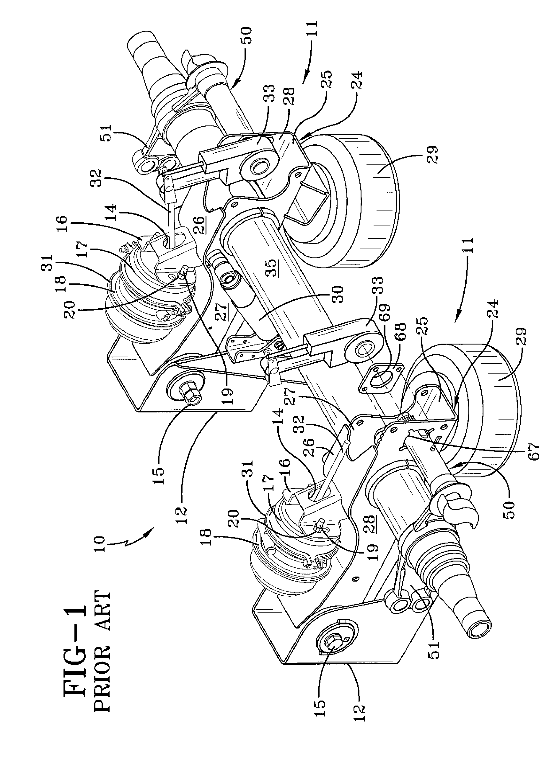
[0032]With reference to FIG. 1, so that the structure, operation and advantages of the improved cam tube bracket of the present invention can be best understood, a prior art cam shaft support / enclosure assembly for a heavy duty vehicle now will be described in the environment in which it is utilized, namely, with a heavy-duty vehicle axle / suspension system 10. Inasmuch as axle / suspension system 10 includes generally identical suspension assemblies 11, each suspended from a respective one of a pair of hangers 12, only one of the suspension assemblies will be described herein.

[0033]In particular; hanger 12 is, by any suitable means, securely mounted on and depends from the underside of the trailer of a heavy duty vehicle, such as a semi-trailer or a full trailer (not shown). A bushing (not shown) is pivotally mounted on hanger 12 by any suitable means such as a fastener 15. The bushing preferably is of the type having multi-functional characteristics. More specifically, the multi-func...


PUM


Abstract

A cam shaft support / enclosure assembly for brake systems of heavy-duty vehicles is mounted on a beam of an axle / suspension system and includes a cam tube. A bracket for mounting the cam tube on the beam includes a pair of plates that are mounted on the beam. Each one of the plates is formed with an opening for receiving the cam tube and includes at least three tabs, and preferably four tabs, that extend outwardly from each respective plate adjacent the opening and contact the outer surface of the cam tube. Each tab includes a generally arched and optionally textured face for mating with an outer surface of the cam tube, which may also be optionally textured, so that when the plates are mounted the tabs engage the cam tube in a press-type fit, minimizing movement of the cam tube.

Description

CROSS-REFERENCE TO RELATED APPLICATION[0001]This application claims the benefit of U.S. Provisional Patent Application Ser. No. 60 / 725,933, filed Oct. 12, 2005.BACKGROUND OF THE INVENTION[0002]1. Technical Field[0003]The invention relates to brake systems of heavy duty vehicles, and in particular to cam assemblies of the brake system. More particularly, the invention is directed to a cam tube bracket for a cam shaft support / enclosure assembly which enables efficient installation, increases load capacity, and offers increased resistance to torsional and axial deflection of a cam tube of the cam shaft support / enclosure assembly, thus reducing fretting and providing a more secure attachment of the cam tube to a suspension assembly, as well as extending the life of the cam shaft support / enclosure assembly.[0004]2. Background Art[0005]In conventional heavy duty vehicle brake systems, an S-cam is utilized to lift brake shoes against a brake drum to decelerate a vehicle. The S-cam is integ...

Claims


Application Information

Patent Timeline
Patent Type & Authority Patents(United States)
IPC IPC(8): B60G9/00
CPCF16B17/006F16D51/00F16D65/28F16B4/004Y10T74/2101F16D2125/56Y10T403/32155Y10T403/32139F16D2125/30
Inventor MORRIS, JEFFPIERCE, PHILLIPPI R.WHITE, JAY D.GREGG, DANE
Owner HENDRICKSON USA L L C
Why Eureka
Try Eureka