
Analog filter with passive components for discrete time signals

a technology of discrete time signals and analog filters, applied in analogue computers, transmission, analog and hybrid computing, etc., can solve the problems of insufficient sinc filter at aliasing frequency, single-pole filter provided downstream of the decimation unit, etc., and achieve the effect of convenient forming

Inactive Publication Date: 2009-05-26
ST ERICSSON SA
View PDF6 Cites 29 Cited by
  • Summary
  • Abstract
  • Description
  • Claims
  • Application Information

AI Technical Summary

Benefits of technology

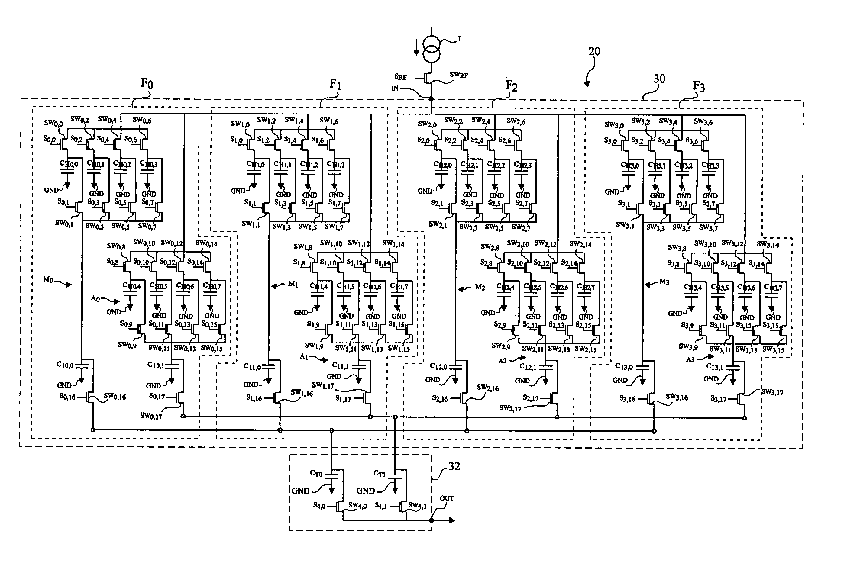
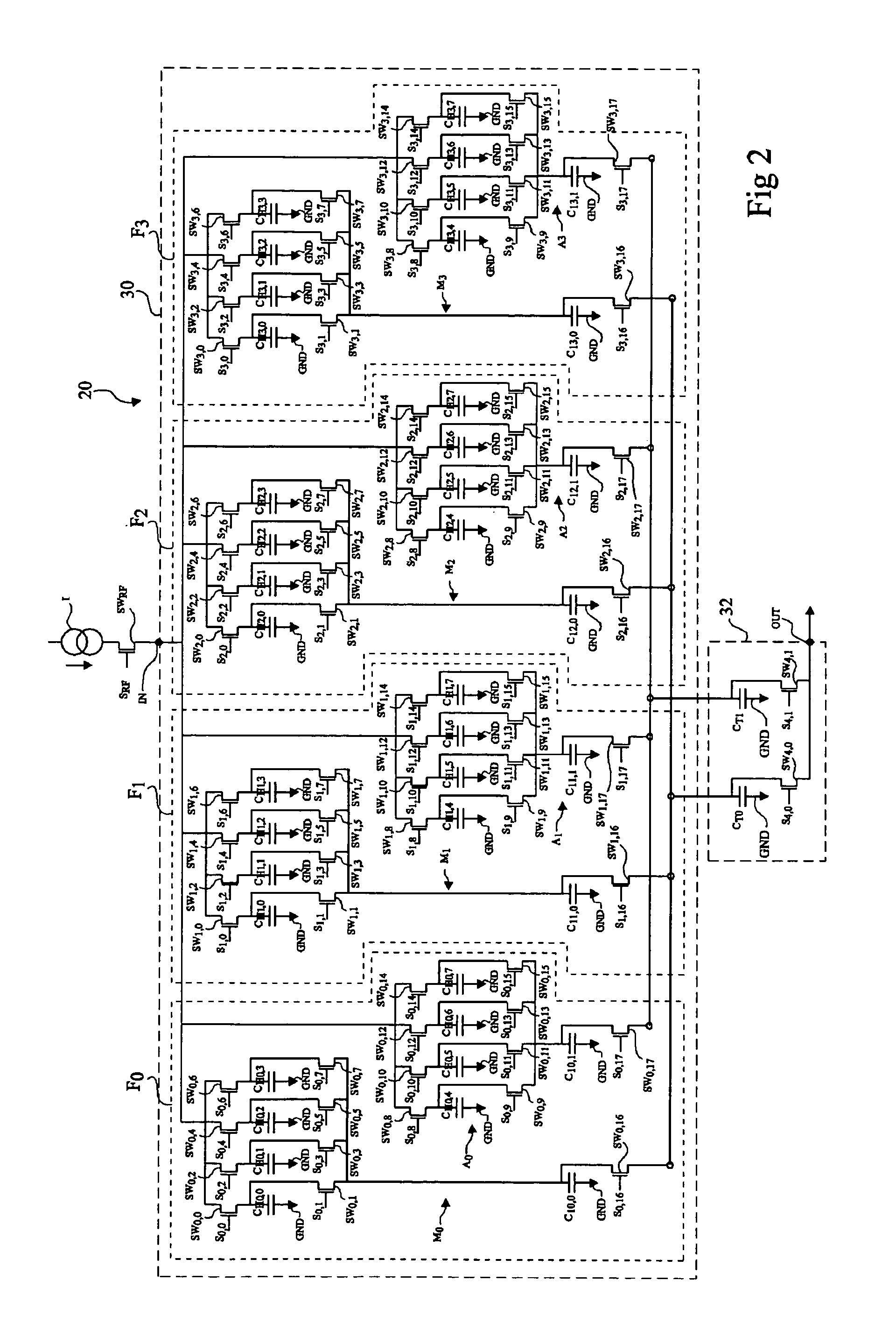
"The present invention provides an original analog filter structure for a discrete time signal that makes it easier to create filters with finite and infinite pulse responses. The filter includes a filtering stage with a determined number of filtering units, each containing head capacitors and an integration capacitor. The head capacitors are connected to the input terminal in a successive clock cycle, while the integration capacitors are connected to the output terminal. The filter also includes means for setting a constant value for the charge stored in each head capacitor after it is connected to the integration capacitor. The capacitances of the head capacitors can be different or the same for each filtering unit. The filter can also have an additional capacitor that is connected to the input terminal and a reference voltage source. The charge stored in the additional capacitor is not set back to a constant value during the filter operation. The invention provides a more efficient and flexible way to create filters for discrete time signals."

Problems solved by technology

However, such filters use operational amplifiers, which may be disadvantageous, especially for systems for which the power consumption must be as low as possible or for which the sampling frequency is high, as is for example the case for radio receivers.
Even though such a filter enables partly limiting the filter aliasing, the attenuation obtained by the SINC filter at aliasing frequencies may be insufficient for certain applications.
Further, the single-pole filter provided downstream of the decimation unit comes too late, since, due to the decimation operation, the spectrum aliasing of the signal provided by the SINC filter has already occurred.

Method used


Image

  • Analog filter with passive components for discrete time signals
  • Analog filter with passive components for discrete time signals
  • Analog filter with passive components for discrete time signals

Examples


Embodiment Construction

[0029]The following discussion is presented to enable a person skilled in the art to make and use the invention. Various modifications to the embodiments will be readily apparent to those skilled in the art and the generic principles herein may be applied to other embodiments and applications without departing from the spirit and scope of the present invention. Thus, the present invention is not intended to be limited to the embodiments shown, but is to be accorded the widest scope consistent with the principles and features disclosed herein.

[0030]Embodiments of the present application will be described for an analog discrete time signal filter used in a radio reception application. However, as will be specified in further detail hereafter, embodiments of the present invention may apply to the forming of any type of discrete time signal analog filter.

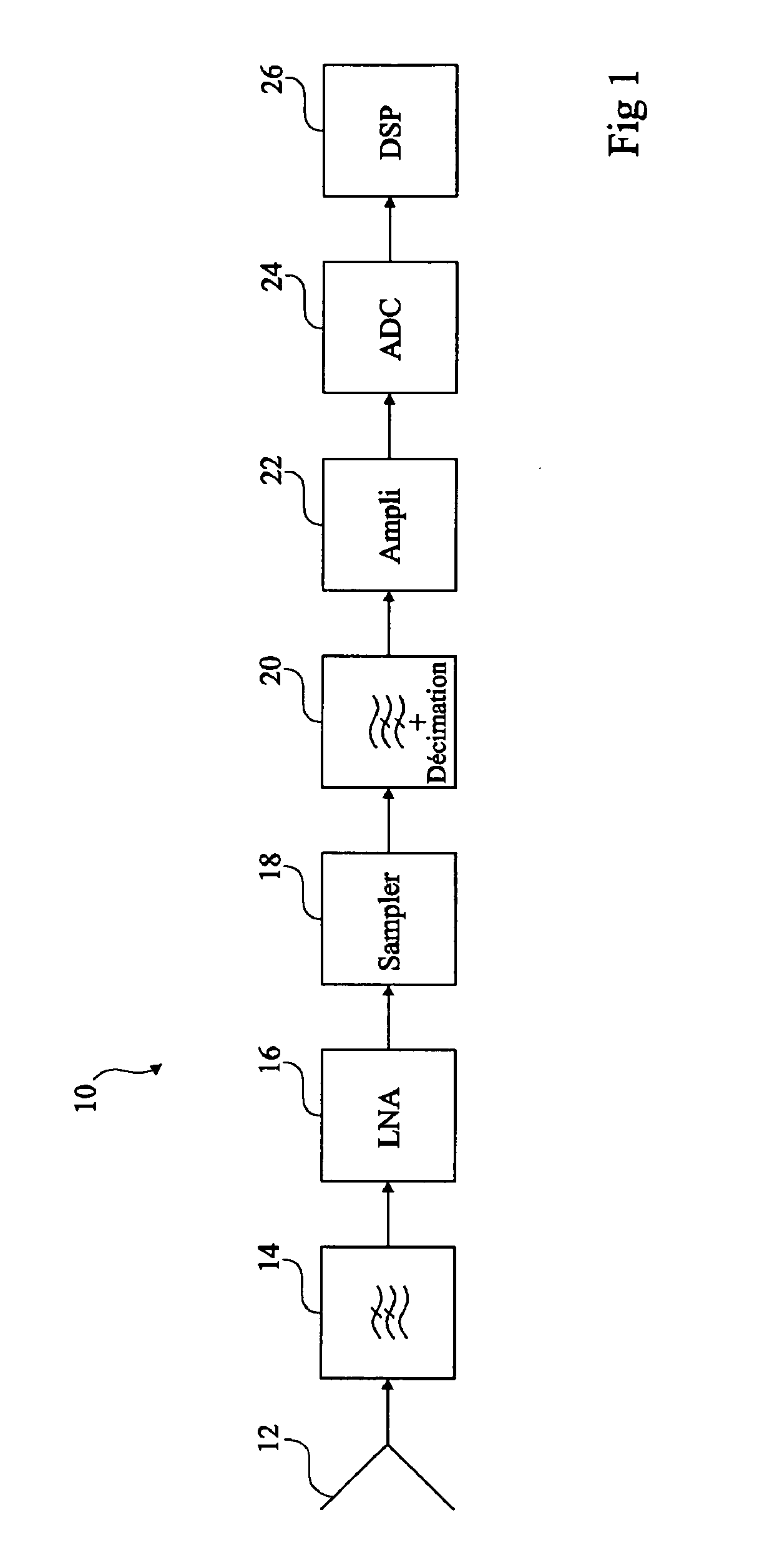
[0031]FIG. 1 shows an example of a radio receiver 10 comprising an antenna 12 providing a high-frequency modulated analog signal to a ...


PUM


Abstract

A filter intended to receive a discrete time signal at a sampling clock frequency, comprising a determined number, greater than 2, of filtering units, each filtering unit comprising head capacitors in a number equal to the determined number, assembled in parallel between an input terminal and the terminal of an integration capacitor; and means for connecting, in successive clock cycles in a number equal to the determined number, successively each head capacitor to the input terminal, and for then simultaneously connecting the head capacitors to the integration capacitor, and in which the successive clock cycles during which the head capacitors of a filtering unit are connected to the input terminal are offset by one clock cycle from one filtering unit to the next one.

Description

PRIORITY CLAIM[0001]This application claims priority from French patent application No. 04 / 52279, filed Oct. 6, 2004 which is incorporated herein by reference.BACKGROUND OF THE INVENTION[0002]1. Field of the Invention[0003]Embodiments of the present invention relate to analog filters for discrete time signals. A discrete time signal is a signal obtained, for example, by sampling an initial analog signal at a determined sampling frequency, and thus corresponding to a sequence of samples of the analog signal not yet converted into binary.[0004]2. Discussion of the Related Art[0005]In signal processing, it may be desirable to perform a filtering operation on a discrete time signal obtained before the discrete time signal is converted into binary. Such a filtering operation enables, for example, limiting the bandwidth of the discrete time signal, especially to avoid aliasing of the signal spectrum when a decimation is performed on the discrete time signal samples before analog-to digita...

Claims


Application Information

Patent Timeline
Patent Type & Authority Patents(United States)
IPC IPC(8): G06G7/02
CPCH03H15/00
Inventor BELVEZE, FABRICEGARCIA, LUC
Owner ST ERICSSON SA
Learn More