High pressure fuel supply pump for internal combustion engine

a fuel supply pump and high pressure technology, which is applied in the direction of liquid fuel engines, machines/engines, positive displacement liquid engines, etc., can solve the problems of reducing the supply property of fuel, lowering the pressure of the pressurizing chamber, and the pressure increasing characteristic of the high pressure pump is apt to be deteriorated, so as to achieve low cost fabrication, easy enhancement of processing accuracy of the seat portion, and preventing the effect of ball valve oscillation

Inactive Publication Date: 2009-06-02
HITACHI AUTOMOTIVE SYST LTD
View PDF34 Cites 30 Cited by
  • Summary
  • Abstract
  • Description
  • Claims
  • Application Information

AI Technical Summary

Benefits of technology

[0046](14) Further, preferably, a ball valve is used for the intake vale or the discharge valve, whereby the processing accuracy of the seat portion can be readily enhanced. Further, a cylindrical member is engaged with the ball valve, and the outer circumference of the cylindrical member is held capable of being reciprocated and slidably moved within the intake passage, so that the oscillation of the ball valve can be prevented. Further, since the cylindrical member is separated from the ball valve, both of them can be fabricated in an easy method.
[0047](15) Further, preferably, in a plunger reciprocating and sliding type pump, a sliding portion of a plunger is made to be a cylindrical member separately from a pump body, whereby only the sliding member can be formed of a material suitable for sliding movement. Further, an inner wall of the cylindrical member is formed with a sliding hole of a plunger and an expanded inner wall portion having a larger inside diameter than the former, and only the outer peripheral portion of the diffused inner wall can be pressed and fitted in the pump body whereby preventing the sliding hole from being deformed. Accordingly, it is not necessary to re-process the sliding hole after fitting the cylindrical member, enabling fabrication at low cost.
[0048](16) Further, preferably, a clearance is provided at a position other than the portion in which the cylindrical member is fitted in the pump body, an annular passage is formed on the outer peripheral portion of the cylindrical member, and the annular passage is made to communicate with one end of the plunger sliding hole and a fuel introducing passage, whereby fuel introducing pressure is guided into the annular passage to reduce a pressure difference relative to the pressurizing chamber, and thus enabling reduction in leakage quantity of fuel when passing through the fitting portion and the sliding portion from the pressurizing chamber. Further, since the fuel covers the outer circumference of the sliding portion, it is possible to cool the sliding portion.
[0049](17) Moreover, preferably, a member in engagement with the pump body and the cylindrical member is provided in the fuel passage whereby the cylindrical member can be prevented from falling off while preventing a leakage of fuel from the engaging portion to the outside the pump or occurrence thereof.

Problems solved by technology

Therefore, immediately after start, the pressure increasing characteristic of the high pressure pump is apt to be deteriorated.
However, in the high pressure fuel supply pump described in Japanese Patent No. 2690734 Specification, an intake passage and a discharge passage are provided on an upper end surface of a pressurizing chamber and an intermediate side wall of the pressurizing chamber, respectively, thus posing a problem in that in the intake stroke, vapor or the like is hard to be discharged on the intake passage side due to the intake fuel, and in the discharge stroke, the vapor or the like is apt to remain within the pressurizing chamber above the discharge passage, thereby lowering the supply property of fuel.
However, both the above-described prior arts have a problem in that since fuel fed from the low pressure pump is communicated with the pressurizing chamber which changes in volume due to piston motion within the high pressure pump, even if an attempt is made to supply fuel to the common rail by the low pressure pump immediately after the engine starts, the piston motion within the pressurizing chamber makes resistance to delay a supply of fuel.
However, this poses a problem in that when an O-ring is formed from an elastic member, it moves due to the pressure variation in the pressuring chamber, and therefore, pressure rising of the pressurizing chamber reduces, or rubbing wear or rupture of the O-ring occurs.
Here, since fuel pressure pressurized is considerably high pressure, fuel possibly leaks out of a clearance between the plunger and the cylinder.
Hei 10-318068 Publication poses a problem in that since the distance from the fuel reservoir (a pulsation reducing space in FIG. 1) in communication with the low pressure fuel chamber to the sliding end of the plunger is short, when the seal material is broken or fallen off, a large quantity of fuel possibly flows outside from a clearance of the plunger sliding portion.
However, since the sliding distance of the plunger from the pressurizing chamber to the fuel reservoir cannot be made long, thus posing a problem in that when pressurized, fuel leaks into the low pressure portion from a clearance of the sliding portion of the plunger to deteriorate the discharge efficiency.
Hei 8-68370 Publication, the distance from the pressurizing chamber to the fuel reservoir is prolonged to thereby enable prevention of a leakage of fuel, but it is necessary, to this end, to prolong the full length of the sliding portion, thus posing a problem in that the whole pump becomes large in size.
As a result, there was a problem in that processing of a pump becomes complicated, and a piping for connecting the pump to the tank is necessary, thus increasing the cost.
However, in such a state of high speed opening and closing, mass of the electromagnetic valve influences on the respondence.

Method used


Image

  • High pressure fuel supply pump for internal combustion engine
  • High pressure fuel supply pump for internal combustion engine
  • High pressure fuel supply pump for internal combustion engine

Examples


first embodiment

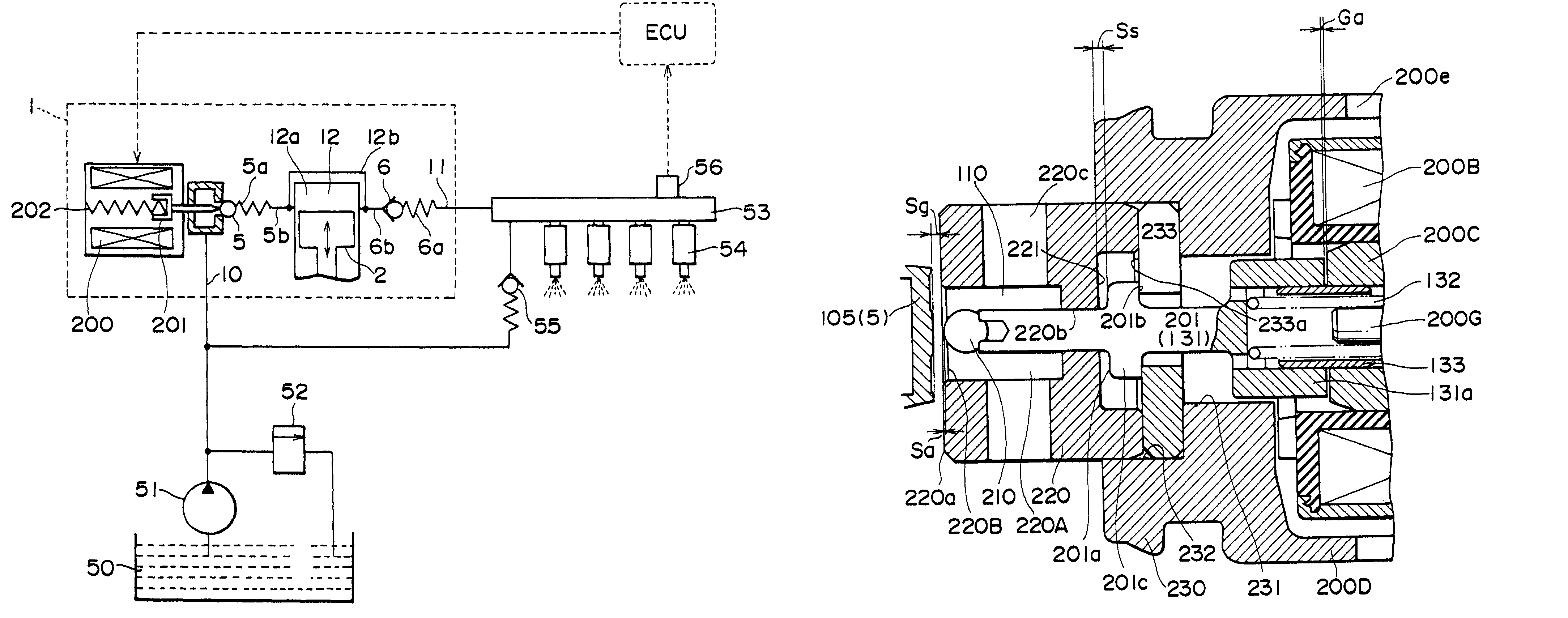
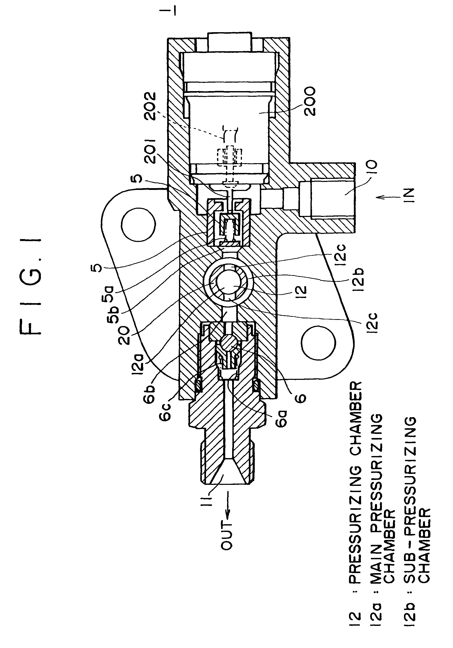
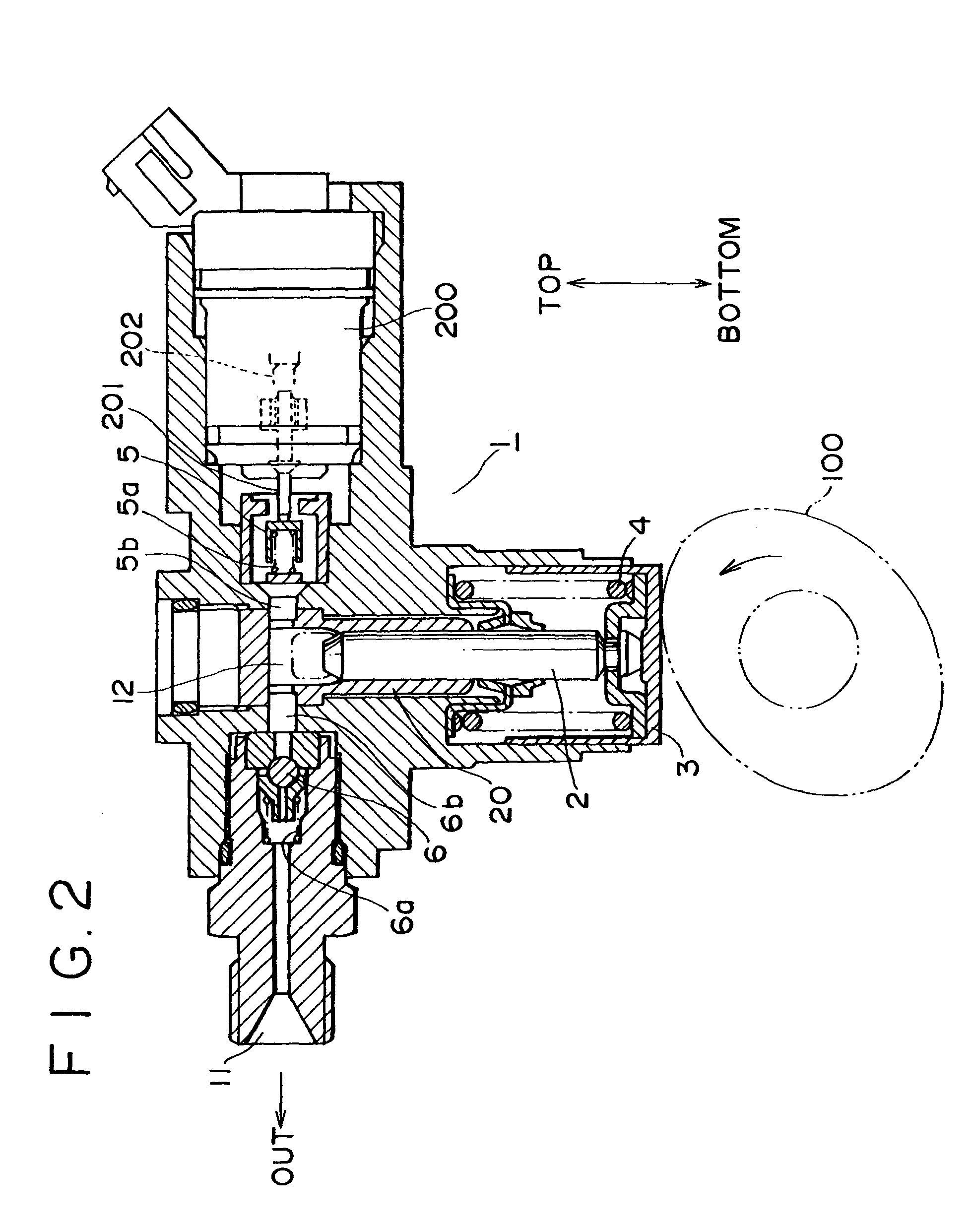
[0067]The constitution of a high pressure fuel supply pump according to the present invention will be described hereinafter with reference to FIGS. 1 to 3.

[0068]FIG. 1 is a horizontal sectional view of a high pressure fuel supply pump according to the present embodiment, FIG. 2 is a vertical sectional view of a high pressure fuel supply pump according to the present embodiment, and FIG. 3 is a system constituent view of a fuel injection system using a high pressure fuel supply pump according to the present embodiment. Note that in the drawings, the same reference numerals indicate the same parts.

[0069]As shown in FIG. 1, a pump body 1 comprises a fuel intake passage 10, a discharge passage 11, and a pressurizing chamber 12. The intake passage 10 is provided with an intake valve 5 in the form of a check valve which is held in one direction by a spring 5a to limit a flowing direction of fuel from the fuel intake passage 10 to a fuel intake passage 5b. The discharge passage 11 is provi...

second embodiment

[0086]The constitution of a high pressure fuel supply pump according to the present invention will be described hereinafter with reference to FIGS. 4 and 5.

[0087]FIG. 4 is a vertical sectional view of a high pressure fuel supply pump according to the present embodiment, and FIG. 5 is a partial enlarged view of FIG. 4. In FIGS. 4 and 5, the same reference numerals as those of FIGS. 1 to 3 indicate the same parts.

[0088]Also in the present embodiment, the pressurizing chamber 12 is provided with the main pressurizing chamber 12a and the sub-pressurizing chamber 12b. The feature of the present embodiment comprises a method of forming the pressurizing chamber 12.

[0089]The pressurizing chamber 12 is formed with a cylinder 20 having a sliding portion of a plunger 2 and being a pressurizing chamber forming portion as well, and a fixing member 30 for fixing the cylinder 20. The inner surface of an upper end portion 20a of the cylinder 20 is in a tapered shape, at which the fixing member 30 c...

third embodiment

[0094]Now, the constitution of a high pressure fuel supply pump according to the present invention will be described with reference to FIG. 6.

[0095]FIG. 6 is a partial enlarged view showing a vertical sectional view of a high pressure fuel supply pump according to the present embodiment. The whole constitution of the high pressure fuel supply pump is similar to that shown in FIG. 4. The same reference numerals as those of FIGS. 1 to 5 indicate the same parts.

[0096]Also in the present embodiment, the pressurizing chamber 12 is provided with the main pressurizing chamber 12a and the sub-pressurizing chamber 12b. The feature of the present embodiment comprises a method of forming the pressurizing chamber 12, which is the other example of those shown in FIGS. 4 and 5.

[0097]In the present embodiment, the periphery of the pressurizing chamber comprises a member for forming a pressurizing chamber 21 which is a member different from the cylinder 20. An upper end portion 21a of the pressuriz...


PUM


Abstract

An intake valve automatically opened and closed by pressure of a pressuring chamber is provided in a fuel intake passage, the intake valve is pushed to open by a plunger of an electromagnetic plunger mechanism, pulling-in operating timing of the plunger is controlled according to the operating condition of an internal combustion engine, and opening time of the intake valve during compression stroke of a pump is controlled to make discharge flow-rate of high pressure fuel variable.

Description

TECHNICAL FIELD[0001]The present invention relates to a high pressure fuel supply pump, and particularly, to a high pressure fuel supply pump suitable for feeding under pressure high pressure fuel to a fuel injection valve of an internal combustion engine.[0002]Further, the invention relates to a high-pressure fuel supply pump provided with a variable capacity mechanism for adjusting quantity of fuel discharged.BACKGROUND ART[0003]① In a conventional high pressure fuel supply pump, for example, as shown in Japanese Patent No. 2690734Specification, fuel is supplied from a tank to a high pressure pump by a low pressure pump to increase its pressure to high, and is supplied to a common rail. Within the high pressure pump, an intake passage and a discharge passage are communicated with an upper end surface of a pressurizing chamber and an intermediate side wall of the pressurizing chamber, respectively.[0004]Further, in the other conventional high pressure fuel supply pump, for example,...

Claims


Application Information

Patent Timeline
Patent Type & Authority Patents(United States)
IPC IPC(8): F02M37/04F02M37/06F02M59/36F02M59/46F02M63/02F04B15/08F04B49/24
CPCF02M59/442F02M63/0017F02M63/0035F02M63/0225F02M59/367F04B15/08F04B49/243F04B53/166F04B1/0421
Inventor YAMADA, HIROYUKITAHARA, SHIGENORISAITO, ATSUJITAKAHASHI, YUKIOABE, MASAMI
Owner HITACHI AUTOMOTIVE SYST LTD
Why Eureka
Try Eureka