Rotary device for transferring containers

a rotary device and container technology, applied in the direction of mechanical conveyors, conveyor parts, transportation and packaging, etc., can solve the problems of increasing the volume of the conveyor device, increasing the difficulty of manufacturing and requiring space, and generating vibration and noise, so as to reduce the number of cams, reduce the number of components, and simplify the structure

Inactive Publication Date: 2009-06-09
SIDEL PARTICIPATIONS SAS
View PDF9 Cites 31 Cited by
  • Summary
  • Abstract
  • Description
  • Claims
  • Application Information

AI Technical Summary

Benefits of technology

[0025]The object of the invention is therefore to respond to the various requirements of the industry and to propose an improved conveyor device which, while remaining capable of providing the function of delivering preforms or gripping finished containers by accompanying the mold through a given angular sector, has a simplified structure with fewer component members and fewer moving members (with a reduced number of cams); which is more compact, thus enabling installations to be made in a generally more concentrated shape; and which can support higher operating speeds.
[0030]Because of the proposed arrangement according to the invention, the transfer arm has a simple structure, without sliding members, and all of its movements are purely rotary. Moreover, the capacity of movement of the rotary arm is reduced to pivoting about its axis of mounting on the plate, so that this pivoting movement can be actuated by a single follower roller engaged in a single cam with two guide tracks opposite each other, or, in order to avoid phenomena of rebound of the roller, with two rollers, one above the other, interacting with a cam with two guide tracks facing each other and offset vertically.
[0031]Admittedly, with a transfer arm designed in this way, the gripping pincer is no longer capable of accompanying the molding axis in a perfectly coaxial way through the predetermined angle of rotation α mentioned above with reference to the prior arrangement. However, it must be borne in mind that the radial difference between the axis of the mold and the pincer, which decreases upstream of the point of tangency D and increases downstream of said point, is in practice very small, typically a few hundredths of a millimeter, or up to a few tenths of a millimeter: it is therefore entirely possible to provide a movement of the transfer which enables the pincer to accompany the axis of the mold as closely as possible, while ensuring that there is no contact between the container supported by the pincer and the wall of the mold. In other words, it is possible to act in such a way that the pincer does not strictly accompany the axis of the mold coaxially with the rotary movement of the latter (which would make it completely certain that there was no contact between the container and the wall of the mold), but follows a trajectory such that the container accompanies the closing or opening movement of the half-mold with the maintenance of a minimum safe distance between this half-mold and the container, thus ensuring that there is contact between them.
[0032]Clearly, the structural simplification of the transfer arm and its actuation results in a conveyor device which is less costly and, which, above all, can operate at substantially higher speeds than those of the existing devices, a factor which, in combination with the improvements also made to other linked devices, enables the whole container manufacturing installation to operate at substantially greater speeds.
[0036]In the latter case, a possible embodiment consists in making the follower roller connected solidly to the second branch of the main arm. In this case, it is useful for the follower roller to be supported by a lever arm which extends approximately transversely to the second branch of the main arm, opposite the first branch. In particular, it is possible to make the first branch and the gripping pincer extend from the same side of the second branch and to make the lever arm extend from the opposite side. This arrangement reduces the grip of the base and enables the arm to be offset.
[0040]By a simple and known method, the pincer is made to be of the type which is automatically returned by a spring to the closed position.

Problems solved by technology

However, these arrangements are structurally complex, using, for example, sliding members as part of the structure of the telescopic arms, which generate friction and consequently wear; this results in the progressive development of play which generates vibration and noise.
Furthermore, the multiple movements of moving parts require the installation of corresponding cams, which are difficult to manufacture and require an amount of space according to their number.
Above all, the conveyor device designed as described above has a large transverse dimension, and the overall bulk of the conveyor device is even more troublesome because the bulk of the devices located at the entrance of the molding device projects from the unit formed by the installation as a whole.
Finally, the multiplicity of the members and the multiplicity of the movements are such that it is impossible to attempt to make the known conveyor device operate at higher speeds than those currently used, even though there is a strong demand for higher output rates among the users of container manufacturing installations.

Method used


Image

  • Rotary device for transferring containers
  • Rotary device for transferring containers
  • Rotary device for transferring containers

Examples


Embodiment Construction

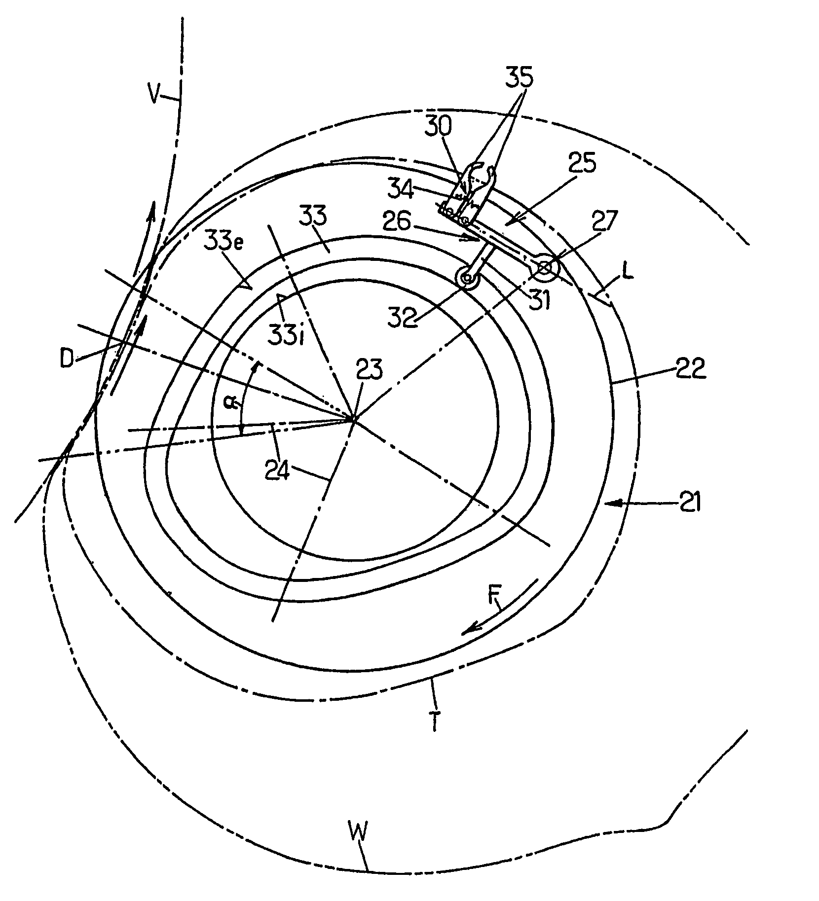
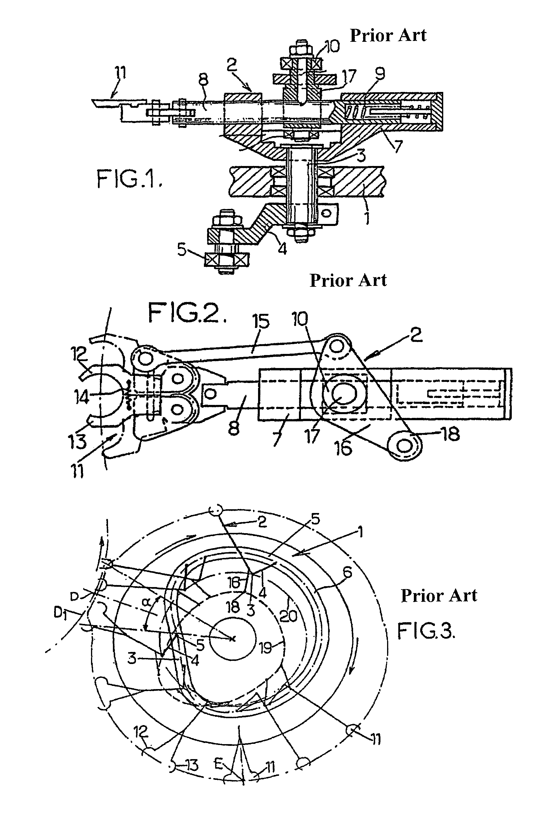
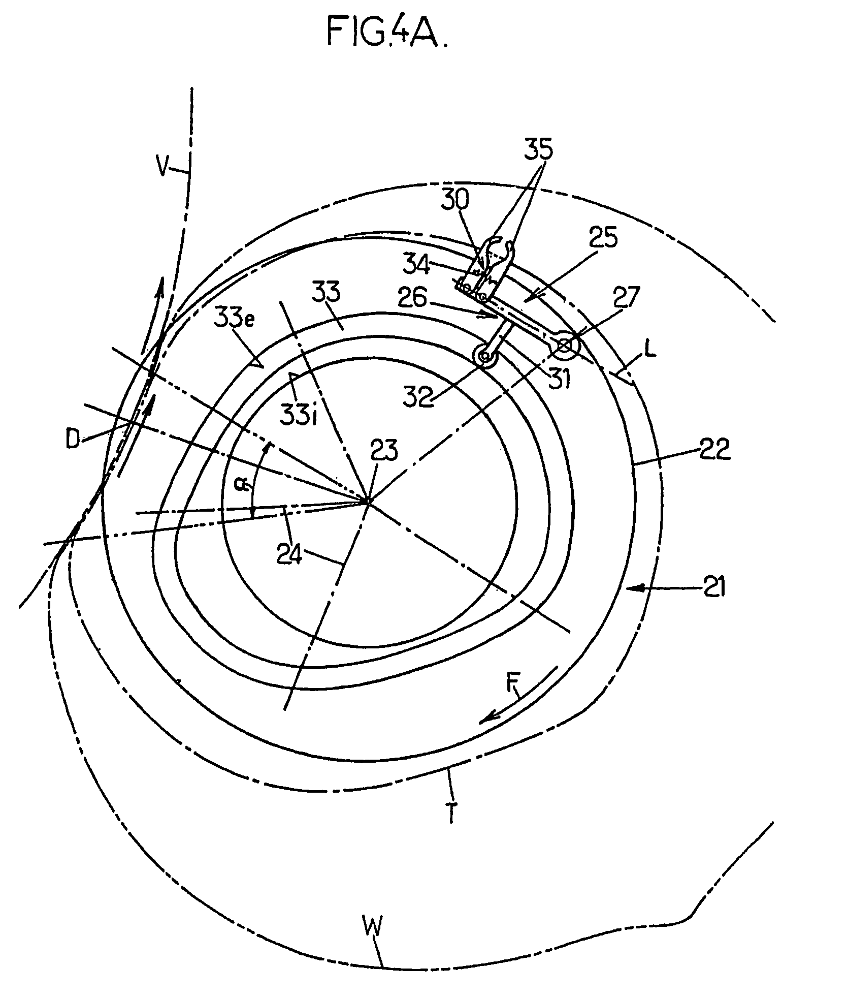
[0050]With reference to FIG. 4A initially, the conveyor device according to the invention has a rotary base 21 (corresponding to the rotary plate 1 of the prior art device) which can advantageously comprise a rotary plate 22 rotating about a vertical axis 23.

[0051]The plate 22 supports at least one mobile assembly 25 (and in practice a plurality of assemblies), which is designed as follows. A main arm 26 is supported pivotably on the plate 22 by means of a vertical shaft 27, the main arm 26 being capable of pivoting in a horizontal plane, substantially parallel to the plane of the plate 22. A gripping pincer 30 is mounted on the free end of the main arm 26, and this gripping pincer 30 extends approximately transversely to the arm 26. Finally, at least one freely rotating follower roller 32 is connected solidly to the main arm 26 and interacts with a fixed cam 33 having a curvilinear profile closed on itself about the axis 23. The roller 32 can be mounted at the end of a lever arm 31...


PUM


Abstract

Rotary device for transferring containers, with a base (21) rotating about an axis (23) and supporting a mobile assembly (25) comprising: a main arm (26) pivoting (27) on the base, a gripping pincer (30) at the free end of the main arm, and a rotary roller (32) which is solidly connected to the main arm and interacts with a fixed curvilinear cam (33) with a closed contour; the pivot shaft (27) and the free end of the main arm define a line (L) which extends approximately tangentially to the circular trajectory of the pivot axis, which precedes the free end of the arm in the direction (F) of rotation of the base; the cam is such that, when the base rotates, the end of the main arm is moved approximately radially; and the gripping pincer mounted on the free end of the main arm follows a predetermined circular path, having inverse convexity with respect to the trajectory of the rotary base, within a fixed angular range (α) of rotation of the base.

Description

FIELD OF THE INVENTION[0001]The present invention relates to improvements made to rotary devices for transferring containers, each having a rotary base which rotates continuously about an axis of rotation and which supports at least one moving assembly comprising:[0002]a main arm mounted pivotably on said base by means of a pivot shaft,[0003]a gripping pincer mounted on the free end of said main arm, and[0004]at least one freely rotating cam follower roller connected solidly to said main arm and capable of interacting with a fixed curvilinear cam extending along a closed contour.[0005]In the following text, the term “container” can be applied, depending on the positioning of the conveyor device within the installation, to a blank container, such as a preform or an intermediate container, before it is placed in a mold, or to a container (final or intermediate) after it has been shaped in a mold.BACKGROUND OF THE INVENTION[0006]The devices to which the invention relates are used in in...

Claims


Application Information

Patent Timeline
Patent Type & Authority Patents(United States)
IPC IPC(8): B65G47/34
CPCB65G47/847B65G2201/0244
Inventor LEGALLAIS, STEPHANE
Owner SIDEL PARTICIPATIONS SAS
Why Eureka
Try Eureka