Driver for induction motor and method of driving the same
a technology of induction motor and drive shaft, which is applied in the direction of motor/generator/converter stopper, dynamo-electric gear control, motor/generator/converter stopper, etc., can solve the problems of failure to lift, large variation in load magnitude, and inability to lift load, etc., to achieve high efficiency
- Summary
- Abstract
- Description
- Claims
- Application Information
AI Technical Summary
Benefits of technology
Problems solved by technology
Method used
Image
Examples
embodiment 1
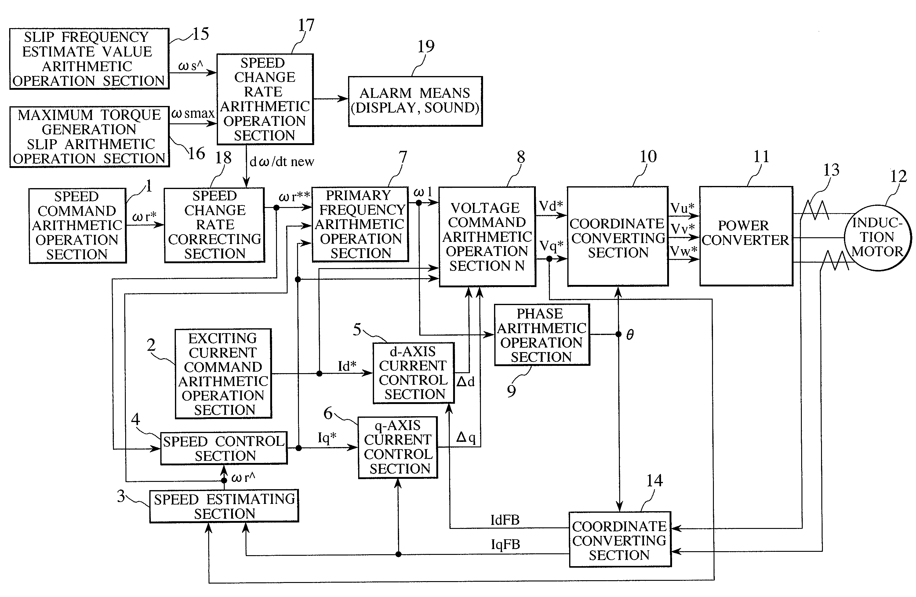
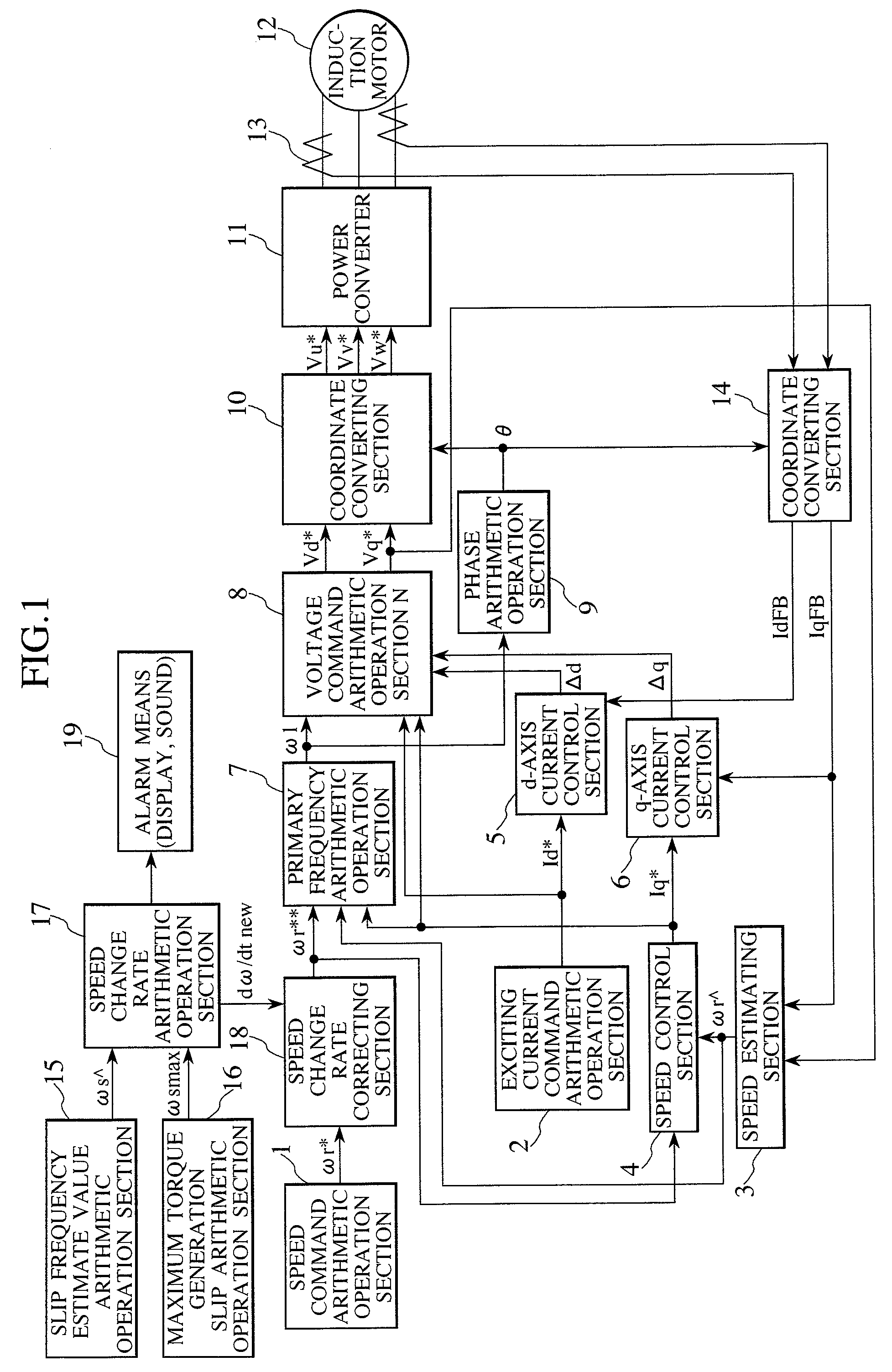
[0025]FIG. 1 is a block diagram showing overall control for a driver for an induction motor according to Embodiment 1 of the present invention. Firstly, a driving control system for an induction motor based on vector control will now be described.
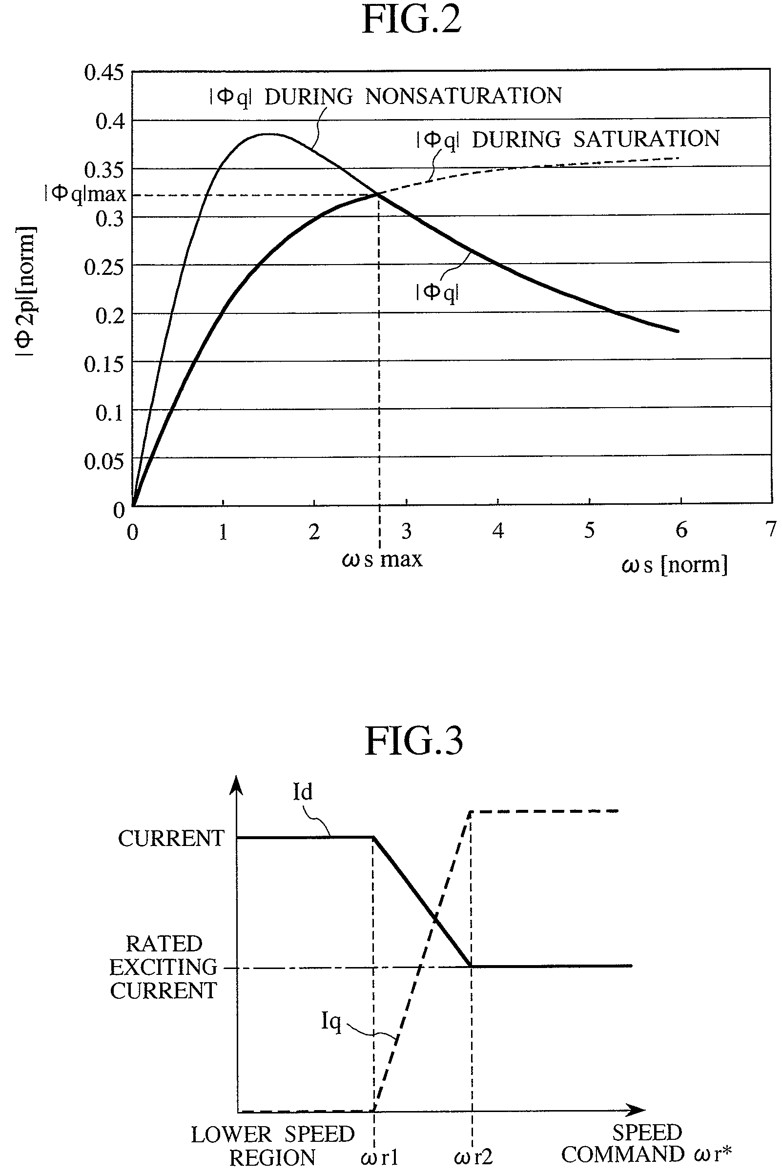
[0026]A speed command arithmetic operation section 1 outputs a speed command ωr*. When an induction motor is accelerated, the speed command ωr* is changed with time at a predetermined rate of change. An exciting current command arithmetic operation section 2 arithmetically operates an exciting current command Id*. A speed estimating section 3 arithmetically operates a speed estimate value ωr^ based on a current feedback value, a voltage command and the like. Note that, various kinds of methods are known as a method of arithmetically operating the speed estimate value ωr^. The present invention can also be applied to another method of estimating the value ωr^ other than the estimating method described in Embodiment 1. A speed control section...
embodiment 2
[0050]A description will now be made of a difference between a driver for an induction motor according to Embodiment 2 of the present invention and the driver of Embodiment 1. For example, there is considered the case where contrary to Embodiment 1, the exciting current Id is held substantially at zero, that is, at Id=0 in the lower speed range, and the q-axis current Iq corresponding to the rated current larger than the normal rated torque current is caused to flow in the induction motor 12. The slip frequency estimate value ωs^ is expressed in the form of a stationary solution obtained by setting Id=0 in Expression (8) by Expression (20). For example, Φ2d^ and Φ2q^ expressed by Expressions (6) and (7) may be used as Φ2d and Φ2q, respectively.
ωs^=1 / Ts·Φ2d / Φ2q (20)
[0051]Suffixes d and q are replaced with each other and a polarity sign is inversed in Expression (10) in Embodiment 1, thereby obtaining the slip frequency ωs^ of Expression (20). Therefore, expressions of the generated ...
embodiment 3
[0052]A description will now be made of a difference between a driver for an induction motor according to Embodiment 3 of the present invention and the driver of Embodiment 1. In Embodiment 3, zero is given as dω / dt2 in the optimal speed change rate arithmetic operation section 173 shown in FIG. 4. As a result, when the rate of change in the speed command ωr* is too large as compared with the load and the slip frequency ωs^ exceeds the threshold ωsmaxTH in the speed change rate setting section 174, the speed change rate setting section 174 outputs zero as dω / dtnew, and the slip frequency command ωr* is fixed in the speed change rate correcting section 18. After that, when the slip frequency ωs^ decreases to a level equal to or lower than the threshold ωsmaxTH, the speed change rate correcting section 18 does not correct the rate of change in the slip frequency command ωr* since the speed change rate setting section 174 outputs the initialized rate of change in the speed. In Embodime...
PUM
 Abstract
Description
Claims
Application Information
 - R&D
- Intellectual Property
- Life Sciences
- Materials
- Tech Scout
- Unparalleled Data Quality
- Higher Quality Content
- 60% Fewer Hallucinations
Browse by: Latest US Patents, China's latest patents, Technical Efficacy Thesaurus, Application Domain, Technology Topic, Popular Technical Reports.
© 2025 PatSnap. All rights reserved.Legal|Privacy policy|Modern Slavery Act Transparency Statement|Sitemap|About US| Contact US: help@patsnap.com


