
Analog front end device

a front end device and analog technology, applied in the field of display systems, can solve the problems of absolute accuracy distortion, analog-to-digital converter, inability to achieve the ideal characteristic of analog-to-digital converter, absolute accuracy distortion of the signal of the single channel, etc., to achieve the effect of increasing the absolute accuracy of a single gain or each individual gain, and increasing display quality

Active Publication Date: 2009-06-09
REALTEK SEMICON CORP
View PDF7 Cites 2 Cited by
  • Summary
  • Abstract
  • Description
  • Claims
  • Application Information

AI Technical Summary

Benefits of technology

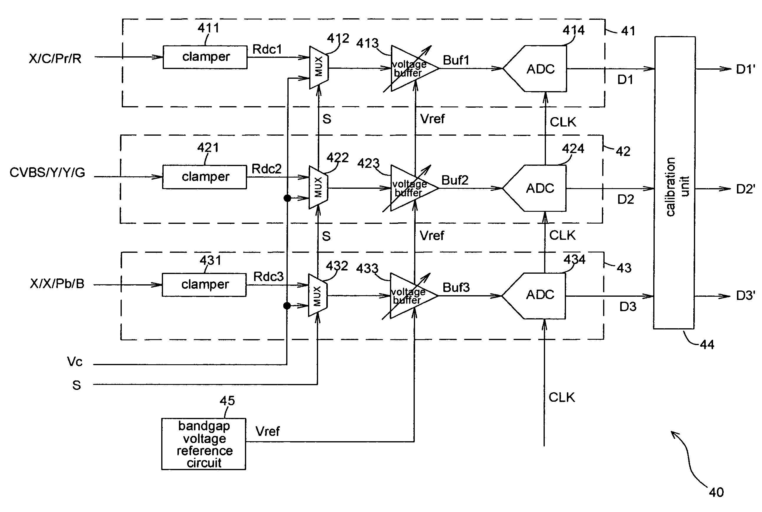
The invention provides an analog front end device that can adjust the absolute gain value and the gain difference between multiple channels. This device includes a conversion circuit and a calibration unit. The conversion circuit generates a clamped signal and a test signal, while the calibration unit uses the test signal to generate a gain correction value and calibrates the gain value of the digital signal. This results in increased gain accuracy and eliminates color shift in the display system, improving display quality.

Problems solved by technology

The digital circuit does not generate offset phenomenon because of the circuit design or influence from manufacturing process, while the analog circuit suffers from the influence of the above-mentioned factors and generates offset or variation, resulting in absolute accuracy distortion phenomenon of the analog-to-digital converter of a single channel or circuit mismatch phenomenon between a plurality of analog-to-digital converters of different channels (for example, between the analog-to-digital converters of the three RGB channels).
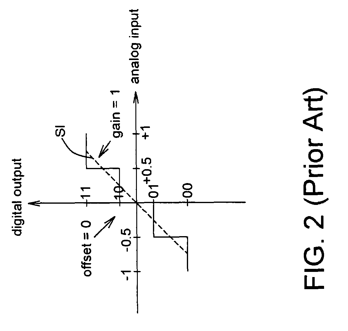
However, the analog-to-digital converter, in reality, cannot achieve the ideal characteristic of an analog-to-digital converter due to imperfect factors, such as process variations.
The above-mentioned imperfect characteristic of the analog-to-digital converter causes the deviations of both the transfer function of the analog-to-digital converter and the absolute accuracy from the expectation in the beginning of the design, resulting in the absolute accuracy distortion of the signal of the single channel.
In a multi-channel display system, such as an original color image display system that has the R,G, B three channels, the mismatch phenomenon between channels arises due to the difference between channels.
Although the offset phenomenon generated by the analog-to-digital conversion can be calibrated by the black level transmitted during the porch interval, there is no effective solution for the imperfect characteristic of the gain, as mentioned in the above.

Method used


Image

  • Analog front end device
  • Analog front end device
  • Analog front end device

Examples


Embodiment Construction

[0022]Before the description of the embodiment of the invention, it should be noted that the display system described in the following embodiments has a plurality of channels (usually, three channels, such as the R, G, and B channels) in order to solve the channel mismatch problem. However, based on the technical content disclosed in the invention, those who are skilled in the art should be able to understand that the invention is not limited to this application area. Even if it is only applied to one single channel among a plurality of channels, the technique of the invention can still solve the problem of a single channel, like the absolute accuracy distortion.

[0023]FIG. 4 shows a schematic diagram illustrating an analog front end device 40 applied in a television system 120 according to one embodiment of the invention. In one embodiment of the invention, a digital-to-analog converter 114 in a video data source system 110 outputs an image analog signal and transmits it to the anal...


PUM


Abstract

The invention discloses an analog front end device includes a calibration unit and at least a conversion circuit. The conversion circuit includes a clamper, a multiplexer, an voltage buffer and an analog to digital converter. The clamper receives an image signal and resets the DC voltage level of the image signal to generate a clamped signal. The multiplexer receives the clamped signal and a test signal and outputs the clamped signal or the test signal according to a selecting signal. The voltage buffer amplifies the clamped signal or the test signal to generate a buffer signal. The analog to digital converter converts the buffer signal into a digital signal. The calibration unit generates a gain correction value according to the test signal and calibrates the gain offset of the digital signal according to the gain correction value.

Description

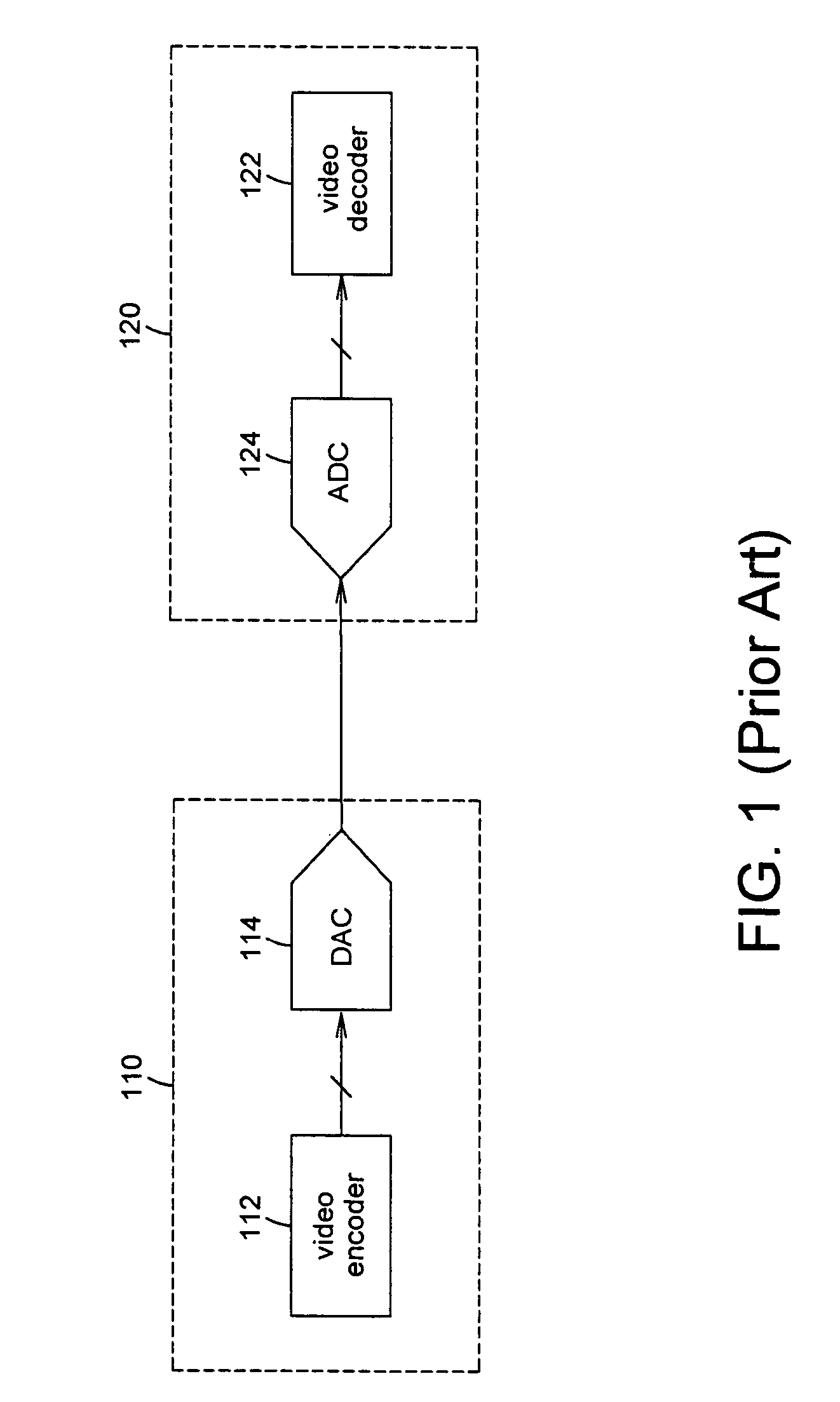
BACKGROUND OF THE INVENTION[0001](a) Field of the Invention[0002]The invention relates to a display system, particularly to an analog front end device of a display system.[0003](b) Description of the Related Art[0004]Since the 20th century, the development of the television technology and its applications has proved that it is now part of human life and entertainment. Because of the improvement of display technology in recent years, providing massive information and high-definition images has become the guideline of future development of the television industry. Please refer to FIG. 1, showing a schematic diagram of a typical television system and its video signal data source. As shown in FIG. 1, the video signal data source system 110 transmits video data in analog signal format to a television system 120 for displaying a video picture. Although digitized transmission interfaces are already available, analog transmission interfaces remain the most commonly used form of interface.[0...

Claims


Application Information

Patent Timeline
Patent Type & Authority Patents(United States)
IPC IPC(8): H03M1/62
CPCH03M1/1028H04N9/642G09G5/006H03M1/123
Inventor TSAI, JUI-YUANKUAN, CHI-KUNG
Owner REALTEK SEMICON CORP
Learn More